
Conclusion
The circuit breaker's rated current is constrained from two directions. The lower bound is set by the circuit breaker itself: ambient temperature in the distribution board and the enclosed enclosure reduce its actual current-carrying capability, so the rated value often needs to be one rating above the calculated current. The upper bound is set by the cable: the corrected conductor ampacity must not be less than the circuit breaker's rated current (GB 50054-2011, Clause 6.3.3, IB ≤ In ≤ Iz).
Both sides must be calculated. Select only from the lower bound and the circuit breaker may be larger than the cable, making overload protection ineffective. Simply move one rating above the calculated current and, inside a cabinet at 40°C, the circuit breaker may trip at full load.
How should circuit-breaker rated current actually be selected?
GB 50054-2011, Clause 6.3.3, expresses the operating characteristics of the overload protective device with two formulas:
IB ≤ In ≤ Iz          (6.3.3-1)
I2 ≤ 1.45 Iz          (6.3.3-2)
Here IB is the calculated circuit current; In is the rated current of a fuse link, the rated current of a circuit breaker, or the setting current; Iz is the permitted continuous current-carrying capacity of the conductor; and I2 is the current that ensures reliable operation of the protective device.
The same requirement appears in Clause 433.1 of GB/T 16895.5-2012, Low-Voltage Electrical Installations—Part 4-43: Protection for Safety—Protection Against Overcurrent, which is identical to IEC 60364-4-43:2008.
The first formula places In between two values: the lower limit ensures that normal full load does not trip the breaker, and the upper limit ensures that the cable is not burned. Both formulas constrain In; they do not tell the designer to multiply calculated current by another margin factor.
Where should temperature and grouping corrections be applied?
In a 40°C electrical room, the conditions act in opposite directions on the circuit breaker and the cable:
| Affected quantity | Condition that makes it smaller | Result |
|---|---|---|
| Iz conductor ampacity (upper bound) | Higher ambient temperature, multiple circuits bundled, enclosed trunking | Upper bound moves down and the available range for In narrows |
| Actual current-carrying capability of In (lower bound) | Higher temperature around the circuit breaker and installation in an enclosed enclosure | Lower bound moves up and a larger rated value is required |
The two sets of factors also have different values:
| Condition | Correction for conductor ampacity | Correction for circuit-breaker current-carrying capability |
|---|---|---|
| Ambient temperature 40°C | 0.91 (GB/T 16895.6-2014, Table B.52.14, XLPE insulation) | 0.93 (Table 4 of a miniature-circuit-breaker data sheet) |
| Four circuits bundled in enclosed trunking | 0.65 (Table B.52.17) | No such concept |
| Circuit breakers installed together in an enclosed cabinet | No such concept | 0.8 (same product data sheet) |
Therefore, the question "should the ambient-temperature factor be multiplied in the numerator or denominator?" is itself wrong: the factor applies to two different quantities. The conductor temperature factor is multiplied by Iz, moving the upper bound down. The circuit breaker's own temperature factor is multiplied by In, moving the lower bound up. The two calculations must be kept separate.
Calculation: what circuit breaker and cable should be used for a 55 kW pump circuit?
Take a 55 kW three-phase pump, 380 V, power factor 0.85, efficiency 0.92:
IB = 55000 ÷ (1.732 × 380 × 0.85 × 0.92) = 106.86 A
The outgoing cable is bundled in enclosed trunking with three other circuits. The distribution room is at 40°C, and the circuit breaker is installed in an enclosed cabinet with the other three circuits.
| Direction | Calculation | Result |
|---|---|---|
| Lower bound (circuit-breaker side) | In ≥ 106.86 ÷ (0.93 × 0.8) | ≥ 143.6 A → select the standard rating 160 A |
| Upper bound (cable side) | Iz = ampacity × 0.91 × 0.65 ≥ 160 | Base ampacity must be ≥ 270.5 A |
| Second condition | I2 = 1.45 × 160 ≤ 1.45 × 183.4 | 232.0 A ≤ 265.9 A, passes |
The base ampacity must be at least 270.5 A. Check a product data sheet for 0.6/1 kV XLPE-insulated four-core copper cable (installed in air, 30°C base condition):
| Cross-section | Data-sheet ampacity | Corrected Iz = ampacity × 0.5915 | Can it carry In = 160 A? |
|---|---|---|---|
| 4×70 mm² | 215 A | 127.2 A | No |
| 4×95 mm² | 265 A | 156.7 A | No |
| 4×120 mm² | 310 A | 183.4 A | Yes |
| 4×150 mm² | 350 A | 207.0 A | Yes (larger margin) |
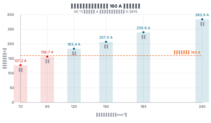
This circuit uses a 4×120 mm² copper cable with a 160 A circuit breaker.
If only the lower bound is used and the circuit breaker's own derating is ignored, a 125 A circuit breaker looks sufficient (125 ≥ 106.86). But inside a 40°C cabinet it can actually carry only 125 × 0.744 ≈ 93 A, below the circuit's full-load current, and will trip during operation.
When does I2 ≤ 1.45Iz actually matter?
First compare the conventional operating currents of two types of circuit breaker at the reference temperature:
| Product standard | Does not operate within the conventional time | Must operate within the conventional time |
|---|---|---|
| GB/T 14048.2-2020 (low-voltage circuit breakers) | 1.05 In | 1.30 In |
| GB/T 10963.1-2020 (household and similar installations) | 1.13 In | 1.45 In |
Substitute each into formula 6.3.3-2:
- 1.45 In ≤ 1.45 Iz; divide both sides by 1.45 → In ≤ Iz, exactly the right-hand part of formula 6.3.3-1;
- 1.30 In ≤ 1.45 Iz → In ≤ 1.115 Iz, about 11.5% less restrictive than formula 6.3.3-1.
In other words, for circuit breakers conforming to these two product standards, once In ≤ Iz is true, the second formula is automatically true. Its real constraint is for protective devices whose conventional operating-current multiple is greater than 1.45.
The result differs for fuses. A gG fuse must melt within the conventional time at 1.6 In. Substituting into formula 6.3.3-2 gives In ≤ 0.9 Iz—a tighter upper bound than for a circuit breaker. If the protective device is changed from a circuit breaker to a fuse on the same circuit, the conductor cross-section may also need to increase.
An adjustable trip is another boundary: if the setting is higher than the rated current, or if the product is not manufactured under the two standards above, the second formula must be calculated separately.
The standard itself leaves a further opening: GB/T 16895.5-2012, Clause 433.1, notes that continuous overloads below I2 may not be protected in some circumstances, in which case a larger conductor cross-section should be considered.
Why can a 105 A circuit have a 160 A circuit breaker?
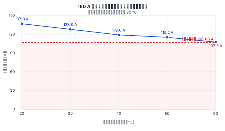
Because the 160 A value was not selected for a 30°C open installation. Under the conditions in the previous section, the actual current-carrying capability of the circuit breaker in a 40°C cabinet is only 74.4% of rated current: 160 × 0.744 ≈ 119 A, just enough to cover the circuit's 106.86 A current.
Conversely, seeing a 160 A circuit breaker on a 105 A load and concluding that it is oversized assumes that the circuit breaker is operating at its reference temperature in an open installation. A distribution board usually does not provide those conditions.
Are rated circuit-breaker current and frame-size rated current the same?
No. Frame-size rated current is the maximum trip-unit rated current that the same enclosure can accommodate. The trip-unit rated current is the In that enters formula 6.3.3.
The number in a product model usually refers to frame size. One frame size can take different trip units: an enclosure with a 100 A frame rating may take 50 A, 63 A, 80 A, or 100 A trip units. The number in the model refers to the enclosure, not the trip unit. When a notation says "100 frame with 200 A," the first number is the frame and the second is In.
An adjustable trip adds another layer. GB/T 16895.5-2012, Clause 433.1, states directly that for an adjustable protective device, In in the formula is the selected setting value—the coordinating value is neither the frame size nor necessarily the rated value.
Does the circuit breaker need to be increased for bundled circuits?
No. Bundling affects only the conductor side: Iz decreases and the upper bound moves down. The remedy is a larger cross-section or more separation, not a larger circuit breaker.
| Installation method (6 circuits) | Ampacity correction factor |
|---|---|
| Bundled in enclosed trunking | 0.57 |
| Single layer on perforated cable tray, touching | 0.73 |
The difference is 28%. Separating the installation does not add material cost; increasing cross-section does.
Questions that still have no answer
- How was the factor 1.45 itself derived? As of 2026-09, the public clauses and explanatory texts searched for this article show only its coordination with other clauses—the conventional operating-current multiple of miniature circuit breakers happens also to be 1.45 In, so the two formulas become equal at In = Iz. They do not show the derivation of the factor.
- The two derating factors are product-data-sheet values, not universal tables. Temperature correction is listed by rated-current range (in the cited sample, the ratio of the 40°C and 30°C values for 25–63 A ranges from 0.92 to 0.94). Enclosure derating depends on the number of units and enclosure sealing. Data sheets usually do not state whether the two factors already include each other; the original wording of the "0.8 In" item is specifically that the "enclosure temperature rises accordingly." Selection must use the data sheet for the product chosen.
- How conservative is multiplying several correction factors? Multiplication assumes that the factors are independent. When high temperature and bundling occur together, the product may be conservative; there is no uniform conclusion about by how much.
Other common questions
Is selecting a smaller circuit-breaker rating safer? No. The lower bound of In is set by "no trip at normal full load." A circuit breaker for household and similar installations should not trip within the conventional time at 1.13 In and must trip at 1.45 In; those values may look like margin, but they apply at the 30°C reference temperature. In a 40°C cabinet, both thresholds move down.
Can In be equal to Iz? Yes. Both formulas become equal at In = Iz. Whether to keep additional margin is an investment decision, not a compliance requirement. The margins that need attention are the step from calculated current to rated current and the gap from rated current to corrected ampacity.
References
All links below were empirically accessible on 2026-09-16 and 2026-09-17. The current status of standards with year numbers was checked against the National Public Service Platform for Standards Information. Because of copyright restrictions, the GB/T standards that identically adopt IEC standards are not provided as online full text; the clause values were additionally checked against manufacturer data sheets conforming to those standards.
- GB 50054-2011, Code for Design of Low-Voltage Electrical Installations, Clause 6.3.3. https://zhc.dicp.ac.cn/GB50054-2011.pdf
- GB/T 16895.5-2012, Low-Voltage Electrical Installations—Part 4-43: Protection for Safety—Protection Against Overcurrent (identical to IEC 60364-4-43:2008), Clause 433.1. https://std.samr.gov.cn/gb/search/gbDetailed?id=yZJkKCjQg0I%3D&mode=p
- IEC 60364-4-43:2008, Clause 433.1 (identically adopted by GB/T 16895.5-2012). https://standards.iteh.ai/catalog/standards/iec/6cb6bb42-afe8-46d9-bd62-90af7028dfee/iec-60364-4-43
- GB/T 16895.6-2014, Low-Voltage Electrical Installations—Part 5-52: Selection and Erection of Electrical Equipment—Wiring Systems, Tables B.52.14 and B.52.17. https://openstd.samr.gov.cn/bzgk/std/newGbInfo?hcno=EDDE2DDF8B79930F2AACFA64F0DFBAF7
- GB/T 14048.2-2020, Low-Voltage Switchgear and Controlgear—Part 2: Circuit-Breakers. https://std.samr.gov.cn/gb/search/gbDetailed?id=FC816D05005D62EBE05397BE0A0AD5FA; its inverse-time operating values (1.05 times no trip, 1.30 times trip, at a +30°C reference temperature) are shown in a circuit-breaker data sheet conforming to the standard. https://dz.chinapeople.com/chanpin/diya/shuijing/RDL20/RDL20.pdf
- GB/T 10963.1-2020, Electrical Accessories—Circuit-Breakers for Overcurrent Protection for Household and Similar Installations—Part 1: Circuit-Breakers for AC Operation, time-current characteristics (1.13 times no trip, 1.45 times trip), current status and copyright information. https://openstd.samr.gov.cn/bzgk/std/newGbInfo?hcno=E36ACE74C13925AA5B294DF4520675F4
- Temperature correction factor table for miniature circuit-breaker rated current (Table 4) and enclosed-enclosure derating factor (product data-sheet basis, 30°C reference temperature). https://m.delixi-electric.com/u/cms/delixi/201807/07225336afgv.pdf
- Ampacity table for 0.6/1 kV XLPE-insulated four-core copper cable (product data-sheet basis, installed in air, 30°C reference). https://www.szjinhuanyu.com/zailiuliang/1433.html
Updated 2026-09. This article is an industry observation and does not constitute procurement advice.