
Conclusion
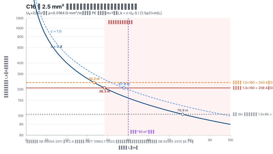
The value to check is not rated current, but the instantaneous-trip setting current. For a Type C miniature circuit breaker, use the upper bound of 10In, not the lower bound of 5In. The threshold is 1.3 times that value (GB 50054-2011, Clause 6.2.4). A worked example with a C16 breaker and a 2.5 mm² socket circuit gives only 159–199 A of earth-fault current at 50 m, while the threshold is 208 A. The circuit already fails before 40 m. When the current is insufficient, the least expensive solution is not more copper: changing from Type C to Type B directly doubles the permitted length.
Which current and which setting are being checked?
Both are easy to select incorrectly.
The current is the minimum after combining three conditions: the minimum system operating mode, a single-phase-to-earth short circuit, and the end of the protected line. The original wording of GB 50054-2011, Clause 6.2.4, says that "the short-circuit current at the end of the protected line shall not be less than ...". In TN and TT systems, this current is calculated as a single-phase earth fault; it cannot be replaced by three-phase short-circuit current.
The setting is the circuit breaker's instantaneous (or short-time) overcurrent trip setting current, not its rated current. For a thermal-magnetic miniature circuit breaker, the setting lies in a range: under GB/T 10963.1-2020, Type B is 3–5In, Type C is 5–10In, and Type D is 10–20In. The standard guarantees tripping at the upper limit (for Type C: no trip at 5In and trip at 10In).
Therefore, the check threshold for C16 is 10 × 16 = 160 A, not 5 × 16 = 80 A. For thermal-magnetic tripping, use the upper end of the multiple range. For an electronic adjustable trip, use the actual setting; the multiple ranges do not apply.
Where does the 1.3-times threshold come from?
The main text of GB 50054-2011, Clause 6.2.4, requires the short-circuit current at the end of the protected line to be at least 1.3 times the setting current of the circuit breaker's instantaneous or short-time overcurrent trip. The explanatory text gives the reason: under current national standard GB 14048.2, the manufacturing tolerance of a circuit breaker is ±20%, and the factor of 1.3 also accounts for calculation error, grid-voltage deviation, and other factors.
One qualification is easy to overlook: this clause applies "when the short-circuit protective device is a circuit breaker." It does not apply to fuses, which must be checked by the method described later.
The GB 14048.2 cited in the explanatory text is currently GB/T 14048.2-2020 (implemented on 2021-04-01 and fully replacing the 2008 edition). When citing it, the safer form is "GB 14048.2 (current edition GB/T 14048.2-2020)."
How is the widely circulated "not more than 50 m" for C16 with 2.5 mm² calculated?
Start with the calculation method. The simplified formula below is widely circulated in Chinese-language material, and the definitions of its parameters are broadly consistent. It is reproduced here on that basis:
I_k = c · U₀ · S / [1.5 · ρ · (1 + m) · L]
U₀ = 220 V (phase conductor to the grounded neutral conductor); S is the phase-conductor cross-section in mm²; ρ is 0.0184 Ω·mm²/m for copper at 20°C; 1.5 is the short-circuit heating-temperature-rise factor (the conductor resistance increases during the short circuit); m = S/S_PE, and m = 1 when the phase conductor and PE have the same cross-section; c is the source-side impedance factor. Public sources give a range of 0.8–1.0 and explain that c = 0.8 corresponds to the upstream feeder having an impedance approximately 20% of the total circuit impedance.
Substitute C16, 2.5 mm², and L = 50 m:
- c = 0.8 → I_k ≈ 159 A
- c = 1.0 (treating upstream impedance as zero) → I_k ≈ 199 A
The threshold is 1.3 × 160 = 208 A. Even if upstream impedance is assumed to be zero, the current at 50 m does not reach the threshold.
Solving for length gives a critical length of 38.3 m at c = 0.8 and 47.9 m at c = 1.0. The widely circulated "not more than 50 m" corresponds to c = 1.0—longer than the critical length calculated under that same assumption. Drawing a curve from it means the circuit has already exceeded its limit.
The result changes with the combination: under the same formula, C6 with 2.5 mm² permits 102 m, while C16 with 4 mm² permits 61 m. Giving a distance without its conditions treats the result for one specific combination as a rule.
Is increasing conductor size useful when end-of-line current is insufficient?
Yes, but it is more expensive than intuition suggests.
From the formula, I_k is proportional to S/(1 + m) and inversely proportional to L. When the phase conductor and PE have the same cross-section, I_k ∝ S/L. Therefore, increasing only PE without changing the phase conductor has little effect—the 1/S term in the denominator remains. To increase the permitted length of C16 with 2.5 mm² from 38.3 m to 100 m, use I_k ∝ S/L in reverse: S must increase to about 6.5 mm², so the standard rating is 10 mm². The phase conductor and PE must be increased together, and copper use is about four times higher.
Conversely, when the two cross-sections are very unequal, the 1/S_PE term becomes dominant and the conclusion reverses. For a combination such as a 240 mm² phase conductor with a 6 mm² PE, increasing only PE is effective—but the combination itself is already non-compliant.
Are there alternatives to adding copper?
Yes, and most are less expensive than adding copper. Set the target as increasing 38.3 m to 100 m:
| Route | Action | Cost and boundary |
|---|---|---|
| Change trip curve | Change C16 to B16, reducing the upper setting limit from 160 A to 80 A | Permitted length doubles to 76 m without adding copper; starting current above 5In may cause nuisance tripping, so this is unsuitable for motors and variable-frequency-drive circuits |
| Shorten the circuit | Move the final distribution box to within 38.3 m | Lowest cost, but constrained by building layout and function |
| Add residual-current protection (RCD) | Separate earth-fault protection from overcurrent protection | No longer subject to the length limit; the explanatory text of GB 50303-2015, Clause 5.1.8, explicitly says that the clause does not consider using an RCD as additional protection, so the two routes are not combined |
| Supplementary equipotential bonding | Use GB/T 16895.21-2020, Clause 411.3.2.6, to move to 415.2 | A compliant alternative when the disconnection time cannot be met; it must be feasible on site |
| Reduce the setting | Directly reduce the setting when an electronic trip is adjustable | Equivalent to changing the curve, but confirm that the load starting current is still cleared |
When can the simplified formula not be used?
The formula above is approximate and assumes that upstream impedance is proportional to line impedance. Written as an explicit impedance relationship, it is equivalent to c = Z_line / (Z_s + Z_line): c = 0.8 means Z_s = 0.25·Z_line, while c = 1.0 means Z_s = 0.
When the circuit is large and long, the assumption breaks down: transformer and low-voltage-bus impedance is fixed and does not increase with line length. Use a 250 A feeder as an example: phase conductor 70 mm², PE 35 mm², upstream (transformer + busway) impedance 0.02 Ω, instantaneous setting 10×250 = 2500 A, and threshold 3250 A.
- Impedance method: Z_s + 1.5ρL(1/70 + 1/35) = U₀/3250 → critical length 40.3 m
- Factor method (c = 0.8) → critical length 45.8 m
The difference is 13.5%. At 40.3 m, the equivalent c under the factor method is only 0.705, already outside its stated 0.8–1.0 range.
The engineering meaning is direct: the simplified formula is adequate for final socket circuits, but a feeder leaving a low-voltage switchboard must explicitly include transformer and bus impedance. Before using any quick-reference table of "maximum permitted length," confirm the upstream-impedance assumption—the same circuit can differ by 20% between a table and the simplified formula. If the table states its calculation basis and the basis matches the project, it can be used directly.
After the design calculation, must the acceptance calculation be repeated?
Yes, and the threshold is stricter.
GB 50054-2011 governs design and gives 1.3 times. GB 50303-2015, Clause 5.1.8, governs construction acceptance and requires the earth-fault loop impedance of the final circuit to satisfy:
Z_s(m) ≤ (2/3) · U₀ / I_a
Multiply both sides by I_a and divide by Z_s(m), then substitute I_k = U₀/Z_s:
I_k ≥ 1.5 · I_a
The acceptance basis is 1.5 times, stricter than the design basis of 1.3 times. The explanatory text says that the factor 2/3 accounts for line-temperature changes.
This clause applies to final circuits where the overcurrent protective device also provides fault protection.
In numbers: for the same C16 with 2.5 mm² circuit, the design critical length is 38.3 m, but under the acceptance basis only 33.2 m remains. The 250 A feeder is shortened from 40.3 m to 32.7 m. These two thresholds are often mixed in Chinese-language material. As of 2026-09, the public sources searched for this article that mention 1.5 times generally do not explain that it comes from the impedance formula in the construction-acceptance standard, nor do they give the 2/3 factor.
Questions that still have no answer
- What is the measured operating error of an electronic adjustable trip? Do manufacturers provide a curve or a single point in their data sheets, and how much do actual trip currents differ at the same setting? Comparing this requires type-test reports from multiple manufacturers; this article does not have them.
- What upstream impedance did each "maximum permitted length" quick-reference table use? Most tables do not disclose their calculation basis, so it cannot be checked.
- How much does the actual operating time of a thermal-magnetic miniature circuit breaker between 5In and 10In depend on the initial state of the bimetal? This requires model-specific test data.
Other common questions
Should a fuse circuit also be checked at 1.3 times? No. The condition in GB 50054-2011, Clause 6.2.4, is "when the short-circuit protective device is a circuit breaker." A fuse must be checked using the product's time-current characteristic curve, including whether it can clear the TN-system distribution circuit within 5 s (Clause 5.2.9 of the same code). The current multiple corresponding to 5 s varies by fuse model, so there is no uniform factor; use the manufacturer's curve.
Can three-phase short-circuit current be used directly for the check? No. Clause 6.2.4 checks the short-circuit current at the end of the protected line. In a TN system this corresponds to single-phase earth-fault current, which is not the same as three-phase short-circuit current. Substituting the three-phase value is optimistic.
References
All links below were accessed on 2026-09-16.
- GB 50054-2011, Code for Design of Low-Voltage Electrical Installations, Clauses 6.2.4 and its explanatory text, and Clause 5.2.9 (current). https://www.mohurd.gov.cn/gongkai/zc/wjk/art/2011/art_17339_206925.html
- GB 50303-2015, Code for Acceptance of Construction Quality of Building Electrical Engineering, Clause 5.1.8 and its explanatory text (current). https://www.mohurd.gov.cn/gongkai/zc/wjk/art/2016/art_17339_226436.html
- GB/T 10963.1-2020, Electrical Accessories—Circuit-Breakers for Overcurrent Protection for Household and Similar Installations—Part 1: Circuit-Breakers for AC Operation. https://std.samr.gov.cn/gb/search/gbDetailed?id=B4C25880C3531CB3E05397BE0A0A92D0
- GB/T 14048.2-2020, Low-Voltage Switchgear and Controlgear—Part 2: Circuit-Breakers. https://std.samr.gov.cn/gb/search/gbDetailed?id=B13990C15C0C5DDAE05397BE0A0A0D35
- GB/T 16895.21-2020, Low-Voltage Electrical Installations—Part 4-41: Protection for Safety—Protection Against Electric Shock, Clauses 411.3.2.6 and 415.2. https://std.samr.gov.cn/gb/search/gbDetailed?id=B691BB778669D126E05397BE0A0AF3B3
- GB/T 16895.23-2020, Low-Voltage Electrical Installations—Part 6: Verification. https://std.samr.gov.cn/gb/search/gbDetailed?id=B691BB77872BD126E05397BE0A0AF3B3
- National Public Service Platform for Standards Information, std.samr.gov.cn (check of current standard editions, 2026-09). https://std.samr.gov.cn/
Updated 2026-09. This article is an industry observation and does not constitute procurement advice.