
Conclusion
A busway's rated current is not calculated by looking up the conductor cross-section in a table. The manufacturer first declares a value and then verifies it with a temperature-rise test: at rated current, the busway is energized until thermal stability, and the temperature rise at every location must not exceed the limit assigned to it in Table 6 of GB/T 7251.1. When the cross-section changes, the result is extrapolated in proportion to the square root of cross-sectional area. So “how many amperes per square millimeter” cannot determine the current—the determining factor is which row of Table 6 becomes the bottleneck. One further point needs attention: the current busway standard anchors its criterion to GB/T 7251.1-2013, but that edition was entirely replaced by the 2023 edition on March 1, 2024.
Who determines the busway's rated current?
The manufacturer declares it. The standard specifies “how to verify it,” not “what it must be.”
Chapter 5 of GB/T 7251.6-2015 adds requirements on the basis of the general rules and gives two expressions that can be written into a catalogue: the rated current of the assembly may be corrected for air temperature (the factor is 1 at 35 ℃), and the rated current of a single circuit may be corrected for air temperature and installation conditions (both factors are 1 at 35 ℃ and the reference installation conditions).
Two easily missed prerequisites are involved: rated current is tied to the installation direction; only a short vertical section of less than 3 m in a horizontal busbar trunking run may disregard the effect of direction. A special incoming arrangement requires a separate agreement; when the incoming unit is not installed at one end of the busbar trunking run or when there is more than one incoming unit, the rated current is agreed between the user and the manufacturer rather than taken from the catalogue.
The rated current is therefore a conditional declared value, not an inherent value derived from material properties.
Which criteria must the temperature-rise test satisfy?
Temperature-rise verification can be completed by testing, or by “deriving the rated current from a similar design.” The test conclusion is brought back to the general rules: at the end of the test, the temperature rise must not exceed the values specified in Table 6. Table 6 is not one number but a table divided by location (excerpt):
| Location | Temperature-rise limit |
|---|---|
| Built-in components | According to the product standard or the manufacturer's instructions for each component, taking the temperature inside the assembly into account |
| Terminals for external insulated conductors | 70 K |
| Busbars and conductors | Limited by the mechanical strength of the conductive material, effects on adjacent equipment, the permissible temperature of insulating materials in contact, effects on connected components, and other conditions; the upper limit is 105 K for copper conductors when all criteria are satisfied |
| Operating handles (metal / insulating material) | 15 K / 25 K |
| Accessible enclosures and cover plates (metal surface / insulating surface) | 30 K / 40 K |
These rows are parallel constraints; exceeding any one of them is a failure.
Why does the “busbar” row in Table 6 say 105 K?
Because the criterion in this row is not one temperature but a list of conditions: the mechanical strength of the conductive material, effects on adjacent equipment, the permissible temperature limit of insulating material in contact with the conductor, the effect of conductor temperature on connected electrical components, and the contact material and surface treatment of plug-in contacts. Copper conductors reach 105 K only when all conditions are satisfied.
There is a reason for 105 K. A comparison of note g in the two editions shows that the 2023 edition changes “bare copper busbars and bare copper conductors” in the 2013 edition to “copper busbars and copper conductors,” and adds that “105 K is related to the temperature at which copper annealing may occur.” The same note also adds—when there is no initial manufacturer's statement on the reliability and stability of electrical-contact or joint aging, a maximum temperature rise of 55 K applies to bare (uncoated) aluminium busbars and conductors.
So the question “what is the temperature-rise limit for a busway?” is not valid by itself—it depends on which location, what material, and which prerequisites are satisfied.
If the cross-section doubles, can the current double?
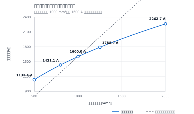
No, not by a long way. The standard gives a derivation rule for busbar trunking units: with the same conductor shape and the same temperature-rise limit, rated current is proportional to the square root of cross-sectional area. Use a test cross-section of “1000 mm², at which a current of 1600 A just reaches the limit” as the baseline:
| Design cross-section | Relative to test cross-section | Allowable current | Relative to baseline |
|---|---|---|---|
| 500 mm² | 0.500 | 1131.4 A | −29.29% |
| 800 mm² | 0.800 | 1431.1 A | −10.56% |
| 1250 mm² | 1.250 | 1788.9 A | +11.80% |
| 2000 mm² | 2.000 | 2262.7 A | +41.42% |
Increasing the cross-section by 25% increases current by only 11.80%; doubling the cross-section increases current by only 41.42%. Conversely, to raise the current by 25%, the cross-section must be increased to 1.5625 times its original value—56.25% more copper. Ampacity is not a linear function of cross-section; cross-section is a means of achieving a rated current, not its source.
If the criterion is relaxed, how much more current can be carried?
If conductor resistance is treated as independent of temperature, the balance between conductor heating and heat dissipation gives a square-root relationship between current and temperature rise. The current ratio between the 70 K and 105 K rows is √(105/70) = 1.2247, or +22.47%.
This calculation is too high. Copper resistance rises with temperature: taking 20 ℃ as the reference and the temperature coefficient as 0.00393 /K, the resistance at a 70 K temperature rise (conductor temperature 105 ℃ at an ambient temperature of 35 ℃) is 1.3340 times the resistance at 20 ℃; at a 105 K rise (conductor temperature 140 ℃), it is 1.4716 times. After including this, the current ratio drops to 1.1661, or +16.61%, 5.86 percentage points below the simple square-root result; the same comparison of 55 K and 105 K falls from +38.17% to +28.61%.
This estimate ignores the faster increase in radiative heat dissipation as temperature rises, as well as the differences in skin and proximity effects at different cross-sections. It can indicate only the order of magnitude and cannot be used as a selection basis.
Where did the online claim “copper 60 K, aluminium 65 K, enclosure 30 K” come from?
There is a traceable source. 60 K, 65 K, and 70 K are the temperature-rise limits for bare-copper, tin-plated, and silver-plated terminals in the low-voltage electrical-apparatus component standard GB/T 14048.1—they govern the component itself, not the assembly. Moving the terminal rows from the component standard over produces statements such as “copper 60 K, aluminium 65 K.”
The treatment of “built-in components” in Table 6 shows the relationship exactly: built-in components follow their own product standard or manufacturer's instructions, but the temperature inside the assembly must be taken into account. The component standard governs how a component heats up in its own environment; the assembly standard governs how the whole system dissipates heat after the component is installed in a cabinet or busway.
The general standard cited by the criterion has changed edition—Which edition should a busway use?
Chapter 2, “Normative references,” of GB/T 7251.6-2015 states that for dated references in this document, only the edition cited applies. Its dated reference is GB 7251.1-2013; Chapter 3, Chapter 5, and other sections also carry forward the 2013 edition with wording such as “this clause of GB 7251.1-2013 applies, except as follows.” GB/T 7251.1-2013 has been entirely replaced by GB/T 7251.1-2023. The 2023 edition took effect on March 1, 2024. As of September 2026, a search for “7251.6” on the National Public Service Platform for Standards Information still returns only one entry, GB/T 7251.6-2015, with current status.
In other words: the temperature-rise criterion for busways is written into a clause chain anchored to an edition that has exited the current standard set, while the new edition happens to change the notes to Table 6. The changes to Table 6 in the 2023 edition are concentrated in notes b, g, and h: note b changes “a lower temperature-rise limit may be adopted” to “a lower temperature-rise limit shall be adopted” and adds that “the thermocouple used for the temperature-rise test shall not be placed on the insulation of the test conductor”; note g adds the prerequisite 55 K limit for bare aluminium busbars; and note h adds that when the daily average air temperature exceeds 35 ℃, a warning label conforming to ISO 7010 W017 should be provided.
Three practical actions follow: state the criterion edition in the technical agreement, rather than leaving it blank; confirm separately for an aluminium-conductor design whether it falls under the 55 K condition; and reserve space for the warning label in a high-temperature installation environment. One distinction is needed: according to the reference relationship in the standard text, only the 2013 edition applies; but when certification and design review are performed against current valid standards, testing and design parties are more likely to compare against Table 6 of the 2023 edition. The conclusion is the same for the 105 K copper-conductor row, while the difference lies in the 55 K limit and the warning label. The whole series makes the situation clearer: Parts 1 and 2 changed edition in 2023, new editions of Parts 5, 7, and 10 were published in 2025, and Part 6 is among those not yet replaced; its last review, in 2021, concluded “revise.” The invalidation condition for this judgment is clear: if GB/T 7251.6 is replaced and points to the 2023 edition or a later edition, the three points above must be rewritten against the new edition.
Can the claim “the new busway national standard takes effect on October 1, 2025” be trusted?
Since 2025, multiple industry articles and manufacturer websites have claimed that two national busway standards fully took effect on October 1, 2025, and have provided details such as the temperature-rise limit being tightened from 65 K to 55 K. Check them item by item:
The number cannot be found. As of September 2026, a search for “7251.6” on the National Public Service Platform for Standards Information returns only GB/T 7251.6-2015.
The other number does not match the name or year. On the platform, GB/T 18859 refers to GB/T 18859-2016, Guide for Testing of Enclosed Low-voltage Switchgear and Controlgear Assemblies under Conditions of Arcing Due to an Internal Fault, which is current; it is neither “enclosed low-voltage busbar trunking systems” nor a 2025 standard.
The numbers do not match either. Table 6 contains no pair in which “65 K is uniformly tightened to 55 K”: 65 K is the tin-plated-terminal row in the component standard, while 55 K is the prerequisite limit newly added for bare aluminium busbars in the 2023 edition.
The only safe record is this: as of September 2026, the public standards-information platform has no entry for that number. This does not mean the document does not exist, but it is sufficient for an operational conclusion—until the standard number is recorded on the platform, do not use this message to revise a technical agreement.
Questions that still have no answer
- When will GB/T 7251.6 change edition, and which edition of the general rules will it cite after the change: the review conclusion is “revise,” but no schedule for a new edition has been published.
- Which operating conditions does the 105 K row apply to: which becomes the bottleneck first—the 30 K enclosure or the 105 K conductor—depends on the structural and heat-dissipation design.
References
- GB/T 7251.6-2015, National Public Service Platform for Standards Information, https://std.samr.gov.cn/gb/search/gbDetailed?id=71F772D80B58D3A7E05397BE0A0AB82A (2026-09-20)
- GB/T 7251.6-2015 public preview, https://www.chinesestandard.net/PDF.amp.aspx/GB7251.6-2015 (2026-09-20)
- List of standards referenced by GB/T 7251.6-2015, Yangzhou Advanced Manufacturing Standard Information Service Platform, https://www.yzbzpt.cn/BzInfoDetail/75f5274f-4097-4931-be6d-5d63c0d5464d (2026-09-20)
- GB/T 7251.1-2023 entry, National Standards Full-Text Publicity System, https://openstd.samr.gov.cn/bzgk/gb/newGbInfo?hcno=DDC142C7F26B5CA1AB759DAA1855E0F2 (2026-09-20)
- Word-for-word comparison of notes b, g, and h in Table 6 of GB/T 7251.1-2023 and the 2013 edition (with standard-page screenshots), technical article by a manufacturer of assemblies, https://www.163.com/dy/article/JJH5A4FK0556A46H.html (2026-09-20)
- GB/T 18859-2016 entry, National Public Service Platform for Standards Information search page, https://std.samr.gov.cn/search/std?q=GB%2FT%2018859-2016 (2026-09-20)
- Distinguishing component-terminal temperature-rise limits from assembly criteria, http://yunrun.com.cn/tech/5112.html (2026-09-20)
- Industry article on “new busway national standard implementation,” busway manufacturer website, https://www.btmxc.com/news/14.html (2026-09-20)
This article is an industry observation and does not constitute procurement advice. | Updated September 2026