
Conclusion
Neither of the two national standards gives a formula. Chapter 6, "Power Supply and Distribution System," of GB/T 50966-2024, Standard for Design of Electric Vehicle Charging Stations, has only six clauses covering wiring, earthing, switch types, reactive-power compensation, and cable selection; none is a capacity algorithm. Chapter 5 of GB/T 51313-2018, Technical Standard for Engineering of Distributed Electric Vehicle Charging Facilities, likewise gives result constraints only. Capacity must be calculated through the chain: rated power → demand factor → efficiency and power factor → apparent capacity → permitted load factor → standard capacity rating. The three places where the chain is most often misapplied all make the result too small. Under the basis used in this article, 30 7 kW AC chargers require 250 kVA, not 125–160 kVA.
What do national standards actually specify for charging-station power supply and distribution?
GB/T 50966-2024 was published on 2024-12-26, implemented on 2025-05-01, and repealed the former GB 50966-2014 at the same time. The six clauses of Chapter 6 can be summarized as follows:
| Clause | Content |
|---|---|
| 6.0.1 / 6.0.2 | Shall comply with Code for Design of Electric Power Supply and Distribution Systems GB 50052 and Code for Design of Substations of 20 kV and Below GB 50053, and facilitate installation, operation, and maintenance |
| 6.0.3 | Medium- and low-voltage distribution systems should use a single busbar or sectionalized single busbar; the low-voltage earthing system should be TN-S; incoming and outgoing switches should preferably be circuit breakers, with mechanical and electrical interlocking between different power sources |
| 6.0.5 | Reactive-power compensation should be installed on the transformer low-voltage side, and capacity should preferably be determined so that the transformer high-voltage-side power factor at maximum load is not less than 0.95 |
| 6.0.6 | Cables should preferably use copper-core XLPE insulation; low-voltage three-phase circuits should preferably use five cores, and single-phase circuits three cores |
"Maximum load" appears twice, but the standard does not say where it comes from. Chapter 6 specifies what the result must satisfy and leaves how to calculate it to the design method.
One revision deserves separate attention. Item 4 of the new edition's foreword says that it "revises power-supply and distribution requirements and deletes power-supply voltage requirements." This chapter is a subtractive revision. The deleted supply-voltage requirement is now handled by Chapter 7, "Power Quality": ±7% for three-phase supply at 20 kV and below, and +7%/−10% for 220 V single-phase supply. Attaching ±7% to Chapter 6 is a widely circulated misattribution.
Why does the new classification of charging stations use the number of charging positions?
The new classification (Table 4.1.3) uses the number of charging positions N:
| Class | Indoor | Outdoor |
|---|---|---|
| Class I | N > 300 | N > 400 |
| Class II | 150 < N ≤ 300 | 250 < N ≤ 400 |
| Class III | 50 < N ≤ 150 | 100 < N ≤ 250 |
| Class IV | 3 ≤ N ≤ 50 | 3 ≤ N ≤ 100 |
From three positions to 400, the unit is consistently "position." Not one value is in kVA—the standard regulates site and facility scale, while electrical capacity is not an input variable.
The question has simply been passed back: Clause 5.1.2 requires that "the rated output current of the charger shall be determined according to the charging station's power-supply capability and the charging demand of the electric vehicles served," but Chapter 6 does not explain how to calculate power-supply capability. This loop is the direct reason no formula can be found.
Where does the capacity formula actually come from?
It comes from national design atlases and manuals, not national standards. The current practice comes from the national building-standard design atlas Design and Installation of Electric Vehicle Charging Infrastructure, 18D705-2: group single-phase AC chargers, three-phase AC chargers, and off-board chargers; select a demand factor Kx for each group; multiply by a coincidence factor Kt; then divide by each group's efficiency η and power factor cosφ.
The method is common, but every parameter still has to be selected. The head of the atlas drafting group said directly at an industry conference in September 2025 that the three load-calculation formulas had received good feedback after seven years in the current edition and did not need revision. But for integrated photovoltaic-storage-charging and managed charging systems there was no better load-calculation method: "When we apply to the utility for how large a transformer to install ... there is still no good solution to the load-calculation problem." The atlas is itself under revision, with publication planned for the second half of 2026.
How should the demand factor be looked up? What is the difference in the "number of units" basis for single-phase AC chargers?
This is the easiest point to get wrong. In 18D705-2's demand-factor curve for 7 kW single-phase chargers, the number of units means the number connected to the same phase, not the total number. When the phases are balanced, the tabulated count can be increased by a factor of three. This basis is not written on the atlas table; it is supplied by local rules and the explanatory clauses of the appendix to T/ASC 17-2021.
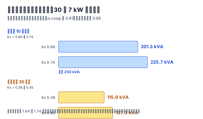
Thirty 7 kW chargers, balanced across three phases:
| Count used for lookup | Kx | Calculated active power | Converted apparent capacity | Divide by 0.85 | Rating selected |
|---|---|---|---|---|---|
| 10 (per phase) | 0.66–0.74 | 138.6–155.4 kW | 171.1–191.9 kVA | 201.3–225.7 kVA | 250 kVA |
| 30 (total) | 0.38–0.45 | 79.8–94.5 kW | 98.5–116.7 kVA | 115.9–137.3 kVA | 125–160 kVA |
The demand factor decreases monotonically with the number of units. Treating the total count as the lookup count gives a demand factor that is too small, leading to an undersized transformer. The two bases differ by 1.64–1.74 times in capacity and, after moving up to a rating, by one to two ratings.
The reverse also needs to be clear: if all 30 chargers really are connected to the same phase, 0.38–0.45 is correct. The basis is wrong only when the distribution side has already balanced the three phases.
One more detail about "7 kW": GB/T 50966-2024, Clause 5.2.1, says that an AC charger with rated current no greater than 32 A may use single-phase 220 V or three-phase 380 V. A single-phase 32 A circuit at full load is 7.04 kW; a three-phase 32 A circuit is 21.06 kW, a difference of 2.99 times.
Why cannot a 7 kW charger be counted as 7 kVA?
The kW on the nameplate is output power. The transformer supplies input-side apparent capacity, with efficiency and power factor between them: S = P ÷ (η · cosφ).
There is a basis for the lower-bound values. T/ASC 17-2021 and Shenzhen SJG 27-2021 both set the minimum power factor of charging equipment at 0.9, while T/ASC 17-2021 also requires efficiency of at least 90%. The 18D705-2 drafting group uses efficiency of approximately 0.95 and power factor greater than 0.90 as common values. Calculate two extremes: with η·cosφ = 0.81, a 7 kW AC charger corresponds to 8.64 kVA and a 60 kW DC charger to 74.07 kVA; with η·cosφ = 0.9025, the values are 7.76 kVA and 66.48 kVA. Input-side capacity must therefore be 10.8%–23.5% above the nameplate, with a conversion factor of 1.108–1.235. Skipping this step and treating kW as kVA under the lower η·cosφ basis underestimates capacity by 19.0%.
Why must calculated capacity be divided by load factor and then moved up to a rating?
Transformers are not intended to operate at full load continuously. Clause 4.3.2 of GB 51348-2019, Standard for Electrical Design of Civil Buildings, says that the long-term operating load factor of a distribution transformer should not exceed 85%; the explanatory text gives economic operation as the reason.
Eighty-five percent is not the only basis. GB/T 51313-2018, Clause 5.2.2, addresses a different situation—adding charging facilities to existing parking spaces. It says to select the connection arrangement based on transformer capacity and the transformer load factor at peak use: no more than 100% for a single-busbar connection and no more than 60% for a sectionalized single-busbar connection. For a 630 kVA transformer:
| Basis | Capacity that can be supported | Applicable situation |
|---|---|---|
| 85% | 535.5 kVA | New build, with the transformer selected by this project |
| 100% | 630.0 kVA | Existing transformer, single-busbar connection |
| 60% | 378.0 kVA | Existing transformer, sectionalized single-busbar connection |
The three values regulate three situations; they are not the upper and lower limits of one scale. Using 100% in place of 85% permits 94.5 kVA more connection capacity. The difference between 60% and 85% is 157.5 kVA, or 1.42 times.
The next rating must also be selected because dry-type distribution transformer capacity is not continuous. Table 1 of GB/T 10228-2023 gives the 6/10 kV capacity series as 30, 50, 80, 100, 125, 160, 200, 250, 315, 400, 500, 630, 800, 1000, 1250, 1600, 2000, and 2500 kVA. A calculated 201.3 kVA can only move up to 250 kVA.
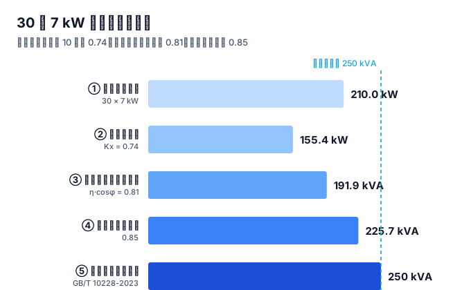
What size transformer is required for 30 7 kW AC chargers?
| Step | Result |
|---|---|
| ① Total rated power | 30 × 7 = 210.0 kW |
| ② Select Kx (10 units per phase) | 138.6–155.4 kW |
| ③ Divide by η·cosφ = 0.81 | 171.1–191.9 kVA |
| ④ Divide by load factor 0.85 | 201.3–225.7 kVA |
| ⑤ Move up to a standard capacity rating | 250 kVA |
If 200 kVA is selected directly, the load factor is 85.6%–95.9%, above 85% at both ends. A 250 kVA unit gives 68.4%–76.7%, or 8.33 kVA per charger.
The purchased capacity is not idle. Long-term monitoring by the 18D705-2 drafting group at a supercharging station showed that the ratio of charging power to equipment rated power averaged about 15%, with a historical maximum below 63%. Applied to the example: the average simultaneous power of 30 chargers is about 31.5 kW, corresponding to 38.9 kVA; the measured peak is about 132.3 kW, corresponding to 163.3 kVA. For a 250 kVA transformer, the load factors are 15.6% and 65.3%, both below 85%.
The two figures are not contradictory. The demand-factor curve serves the one-time decision of selecting a transformer and must account for the worst simultaneous case; 15% describes normal utilization.
What are group-controlled and managed charging changing?
The new edition adds term 2.0.9, "group-controlled charging": dynamically allocating the output power of multiple charging interfaces according to charging demand and system-load conditions. Clause 5.1.7 correspondingly says that off-board chargers for group-controlled charging should preferably use a split one-machine/multiple-charger structure, with power units centralized and terminals sharing charging power, and should provide dynamic power allocation and load-control functions.
The implication for capacity calculation is that the demand factor was originally a discount observed after the fact, assuming each charger operates independently. Group control and load management turn it into pre-event control; the power allocation itself suppresses the peak. The discount factor is being replaced by control capability.
Questions that still have no answer
There is no corresponding factor for managed charging. The drafting group says that no suitable load-calculation method currently exists for this scenario. For a project capable of managed charging, whether Kx can be below the curve and by how much has no public basis.
Can measured utilization support reducing the factor? The 15% figure comes from a supercharging station, whose vehicle mix and turnover are higher than ordinary residential slow charging. Applying it directly would underestimate demand. As of 2026-09, the public sources searched for this article did not provide long-term monitoring data by scenario.
How should the basis be adjusted for three-phase imbalance? When the phases are not evenly balanced, the number of units must be taken by phase. There is no public method for converting the resulting phase imbalance into one capacity value.
References
All links below were accessed on 2026-09-18. Item 3 is a reproduction on a technical standards website because the standard has no official free full text.
- Ministry of Housing and Urban-Rural Development notice on issuing the national standard Standard for Design of Electric Vehicle Charging Stations (2024 No. 230). https://www.mohurd.gov.cn/gongkai/zc/wjk/art/2025/art_ec12df875bda4bc098bd389075dcb201.html
- GB/T 50966-2024, Standard for Design of Electric Vehicle Charging Stations, full text; foreword and Chapters 3, 4, 5, 6, and 7 checked clause by clause. https://xxgk.qinshui.gov.cn/xzf/qsnyj/fdzdgknr/gzdt/202508/P020250826331926464772.pdf
- GB/T 51313-2018, Technical Standard for Engineering of Distributed Electric Vehicle Charging Facilities, Chapter 5 clauses and explanatory text. https://www.gdgooven.com/document9/6906.html
- Li Binghua, "Analysis of Several Key Issues in the Revised National Building Standard Design Atlas Design and Installation of Electric Vehicle Charging Infrastructure," speech transcript from the 2025 China Automotive Charging and Swapping Ecosystem Conference. https://www.evcipa.org.cn/newsinfo/10854583.html
- GB 51348-2019, Standard for Electrical Design of Civil Buildings, Section 4.3 clauses and explanatory text. https://gf.cabr-fire.com/article-16725.htm
- Demand-factor bands for single-phase 7 kW chargers: Table 4.3.3 of Guangdong standard DBJ/T 15-150-2018 (the explanatory text says it was adjusted from national atlas 18D705-2). https://www.zhanjiang.gov.cn/fileserver/news/747bc433-6787-47af-b724-7a8f15950adc.pdf
- GB/T 10228-2023, Specification and Technical Requirements for Dry-Type Power Transformers, Table 1 capacity series. http://www.js.sgcc.com.cn/images/xxgk/gwjssdlyxgs/jsdz/2025/12/16/1450528529437171712.pdf
- Current status and replacement relationship of GB/T 10228-2023. https://www.wzisps.org.cn/Bz/Detail/0847F9B5-715A-4D1E-BA76-AAA61E9EF30A
This article is an industry observation and does not constitute procurement advice.