
Conclusion
Using a table is only the starting point. The current table is Table 54.2 (the old edition used Table 54.3). It is tied only to phase-conductor cross-section and does not know the circuit length or the circuit-breaker setting. Whether PE is sufficient is actually determined by two tests: thermal stability and protective sensitivity. A 250 A circuit provides an example: the 35 mm² PE selected from the table leaves the end-of-line earth-fault current below 1.3 times the instantaneous-trip threshold once the circuit exceeds about 40 m. Increasing PE to 300 mm² still cannot solve it—this circuit has a theoretical upper limit.
Is this table Table 54.2 or Table 54.3?
Search for "how to select PE conductor" and you will probably find "Table 54.3 of GB 16895.3." That belongs to the 2004 edition: GB 16895.3-2004 (identical to IEC 60364-5-54:2002), Clause 543.1.1, says that the cross-section of a protective conductor may be selected according to Table 54.3.
The current edition uses Table 54.2. The table was renumbered after the revision. The contents of IEC 60364-5-54:2011 and its 2021 amendment call it "Table 54.2, Minimum cross-sectional area of protective conductors (where not calculated according to 543.1.2)." The Chinese standard has also changed: GB/T 16895.3-2024 was published on 2024-12-31, implemented on 2025-07-01, and fully replaced GB/T 16895.3-2017, identically adopting IEC 60364-5-54:2021 (National Public Service Platform for Standards Information entry). Confirm the edition first.
The three size bands are unchanged (GB/T 16895.3-2024, Table 54.2, where the phase and protective conductors use the same material; a different material requires k₁/k₂ correction):
| Phase-conductor cross-section S (mm²) | Minimum protective-conductor cross-section (mm²) |
|---|---|
| S ≤ 16 | S |
| 16 < S ≤ 35 | 16 |
| S > 35 | S / 2 |
But the table is only one of two routes. The current standard's Clause 543.1.1 says:
The cross-section of the protective earthing conductor may be calculated according to the formula in 543.1.2, or selected according to Table 54.2. Both methods shall take the requirements of 543.1.3 into account.
Clause 543.1.2 gives the calculation method: when disconnection time does not exceed 5 s, S ≥ √(I²t)/k; above 5 s, IEC 60949 should be used to account for non-adiabatic heating. Clause 543.1.3 addresses a different issue: a protective conductor that is not part of a cable and is not in the same enclosure as the line conductors must be at least 2.5 mm² (with mechanical protection) or 4 mm² (without mechanical protection) copper.
In engineering language, there are two gates: thermal stability—PE must not burn when fault current flows—and sensitivity—fault current must be high enough for the protection to clear within the required time. Table 54.2 is a simplified table for "ordinary conditions." Its cost is that it is only a function of phase-conductor cross-section.
Why does the same table give the same answer for a 15 m circuit and a 150 m circuit?
Because circuit length is not a variable in the table at all. Use a common TN-S industrial-plant circuit: a 630 kVA, Dyn11 transformer, Uk = 6%, a 250 A moulded-case circuit breaker (thermal-magnetic), instantaneous setting 10 In = 2500 A, YJV-4×70+1×35 copper-core XLPE cable, 70 mm² phase conductor, 35 mm² PE, and variable length L.
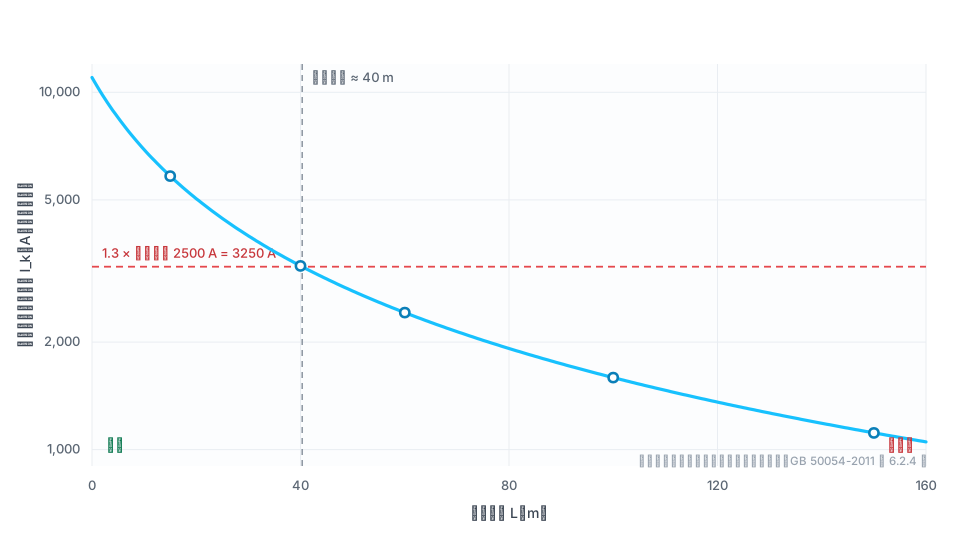
Parameters: U₀ = 220 V, ρ = 0.0184 Ω·mm²/m, short-circuit heating factor 1.5, and source impedance Z_s = 0.02 Ω. Calculate end-of-line single-phase earth-fault current from the phase-to-PE loop impedance: I_k = U₀ ÷ [Z_s + 1.5ρL(1/S + 1/S_PE)]. The results below use that formula:
| Cable length L (m) | Phase-to-PE loop impedance (Ω) | End-of-line earth-fault current I_k (A) | Is it ≥ 3250 A? |
|---|---|---|---|
| 15 | 0.0377 | 5829 | ✅ Meets |
| 40 | 0.0673 | 3268 | ⚠️ Critical |
| 60 | 0.0910 | 2418 | ❌ Does not meet |
| 100 | 0.1383 | 1591 | ❌ Does not meet |
| 150 | 0.1974 | 1114 | ❌ Does not meet |
The critical length is about 40 m (exact value 40.3 m). Once this 250 A circuit exceeds 40 m, it can no longer rely on the circuit breaker's overcurrent protection alone for earth-fault protection—yet over the entire range, the Table 54.2 check of PE cross-section always gives "35 mm², compliant."
The parameters are illustrative. Actual engineering calculation of single-phase earth-fault current should handle transformer zero-sequence impedance and line reactance under GB/T 15544.1. Reactance is ignored here to show the order-of-magnitude relationship between the criteria.
Thermal stability: is the 35 mm² selected from the table sufficient?
The adiabatic check is S ≥ √(I²t)/k. For a PE inner conductor in a multicore cable with XLPE insulation, k = 143 (initial 90°C, final 250°C; GB/T 16895.3-2024, Annex A, Table A.54.4). Consider two endpoints:
Case 1: short circuit, fast protection. At L = 15 m, take the most unfavorable fault near the cable origin. Loop impedance is almost only the source-side impedance, so I_k ≈ 220 ÷ 0.02 = 11,000 A, with a trip time of about 0.02 s.
I²t = 11,000² × 0.02 ≈ 2.42 × 10⁶ A²s → S ≥ √(2.42 × 10⁶) ÷ 143 ≈ 10.9 mm²
The 35 mm² required by Table 54.2 is conservative by a factor of 3.2 here.
Case 2: long circuit, slow protection. At L = 150 m, end-of-line fault current is only 1114 A, below the instantaneous-trip threshold. It can only rely on long-time tripping, with operation in the range of tens of seconds (take 20 s for illustration):
I²t = 1114² × 20 ≈ 2.48 × 10⁷ A²s → S ≥ √(2.48 × 10⁷) ÷ 143 ≈ 34.8 mm²
Here, the 35 mm² from Table 54.2 is just sufficient. Two boundaries matter: 0.02 s is within the range highlighted by GB 50054-2011, Clause 6.2.3—when duration is less than 0.1 s, the influence of the aperiodic component should be included, and engineering practice should check the circuit breaker's I²t let-through-energy curve; the adiabatic formula applies up to 5 s, so the 20 s example is beyond its range, and using 5 s gives about 17.4 mm².
The 1/2 rule therefore resembles an empirical calibration from an era when protection did not operate quickly: it wastes copper in fast-protected circuits and just covers slow-protected circuits. The table is not wrong; it was never intended to answer whether protection is fast or slow.
Protective sensitivity: is increasing PE useful when the breaker will not trip?
Table 54.2 does not address this at all. GB 50054-2011, Clause 6.2.4, requires:
When the short-circuit protective device is a circuit breaker, the short-circuit current at the end of the protected line shall not be less than 1.3 times the setting current of the circuit breaker's instantaneous or short-time overcurrent trip.
Why 1.3? The explanatory text says that, under the then-current national standard GB 14048.2, the manufacturing tolerance of the circuit breaker was ±20%, in addition to calculation error, grid-voltage deviation, and other factors. In this example, the threshold is 1.3 × 2500 = 3250 A; the 40 m point in the table (3268 A) is just above it, while 60 m no longer meets it.
There is also a time requirement. GB/T 16895.21-2020, Clause 411.3.2.3, states that the disconnection time for a distribution circuit in a TN system must not exceed 5 s (for final circuits, use 0.4 s from Table 41.1). At 150 m the fault current is only 1114 A, approximately 4.5 In, and long-time tripping takes tens of seconds—this is not only "insufficient sensitivity"; it also fails the 5 s requirement.
A common field route (a constructed scenario, not a specific project) illustrates the problem: the original final box was about 30 m from the transformer, with I_k ≈ 3965 A and compliance. A new load was added in another building and the circuit was extended to about 160 m, with I_k ≈ 1051 A. The drawing review checked ampacity, voltage drop, and PE cross-section—three items passed, but nobody recalculated the end-of-line earth-fault current, and the circuit-breaker setting did not change. The changed quantity was circuit length, precisely the variable that does not exist in Table 54.2.
When a field circuit will not trip, the most common response is to increase PE—but for this circuit it does not work. Fix L = 150 m and change only PE:
| PE cross-section (mm²) | Phase-to-PE loop impedance (Ω) | End-of-line earth-fault current (A) | Distance from 3250 A threshold |
|---|---|---|---|
| 35 (Table 54.2 value) | 0.1974 | 1114 | Short by a factor of 2.9 |
| 70 | 0.1383 | 1591 | Short by a factor of 2.0 |
| 150 | 0.1067 | 2061 | Short by a factor of 1.6 |
| 300 | 0.0929 | 2367 | Short by a factor of 1.4 |
| Theoretical limit (PE → ∞) | 0.0791 | 2780 | Still short by a factor of 1.2 |
Using more than four times the copper raises fault current only from 1114 A to 2061 A. This route also has a ceiling: the phase-to-PE loop consists of source impedance and phase-conductor impedance in series, so making PE larger can only remove one term. The theoretical limit is 2780 A, which never reaches 3250 A—the main limitation is not PE, but the phase conductor and the source.
What can be done without spending money on copper?
First choice: change the protection method. Reduce the instantaneous-trip setting from 10 In to 5 In (1250 A). The threshold becomes 1.3 × 1250 = 1625 A. Recalculate the critical length: Z ≤ 220 ÷ 1625 = 0.1354 Ω; cable impedance term ≤ 0.1154 Ω; L ≤ approximately 97.5 m. Not one unit of copper is added, and the critical length extends from 40.3 m to 97.5 m.
Second, the standard provides another route. GB/T 16895.21-2020, Clause 411.3.2.6, says that when the required automatic-disconnection time cannot be met, supplementary protective equipotential bonding should be applied under 415.2. When the circuit cannot be shortened in practice, adding equipotential bonding is a standards-based compliant option, not a workaround.
Only then consider adding copper. If protection and bonding must remain unchanged, both phase conductor and PE must be increased. Under the same model, each must be at least about 174 mm², meaning both must move to the 185 mm² rating (four rating steps up from 70 mm²). I_k then becomes approximately 3397 A, just above the threshold; the economics are generally unattractive.
The points above apply to new-build or retrofit circuits that are long and whose final equipment needs earth-fault protection. For ordinary short circuits, the table result remains usable.
Questions that still have no answer
The public sources searched for this article as of 2026-09 did not give a clear basis for the following questions, so they are not presented as conclusions:
- Is 1.3 times still sufficient? The explanatory text gives its reason based on product performance at the time. The error characteristics of electronic trips and current-limiting circuit breakers are different today, but public sources do not appear to have re-argued whether this factor remains suitable.
- What is the actual let-through energy of an electronic trip's "short-time" function? Reducing the setting to 5 In is the calculated optimum for this circuit, but whether a particular breaker can meet the 5 s disconnection requirement at 97.5 m depends on its trip curve and must be checked model by model.
- How should source-side impedance be selected for an existing retrofit circuit? The 0.02 Ω used here is illustrative. An existing plant needs field measurement, while public sources differ on where the measurement should be taken and whether transformer zero-sequence impedance is included. This is one of the questions that this article cannot currently answer.
The reason for retaining this section is simple: the criteria are clear, but parameter selection and product data depend on the project. Any judgment without public support is left out of the preceding conclusions.
Other common questions
Can PE be smaller than the phase conductor?
Yes. The standard explicitly allows it. When S > 35 mm², using half the phase-conductor cross-section is allowed, provided the two gates above are passed. What cannot be reduced is a separate PE that is not installed in the same enclosure as the cable: GB/T 16895.3-2024, Clause 543.1.3, requires at least 2.5 mm² copper with mechanical protection or 4 mm² without mechanical protection. This is a parallel rule to Table 54.2, and many references cite only the table and omit it.
Can this calculation be replaced by the simplified formula?
The engineering hand calculation commonly uses I_k = (0.8–1.0)·U₀·S ÷ [1.5·ρ·(1+m)·L], where m is the ratio of phase-conductor to PE cross-section. It is usable for long circuits. But source impedance is a large share of the total in short circuits, so the simplified formula can significantly overestimate current: with the parameters above, at L = 15 m the simplified formula gives 9,919–12,399 A, while the exact formula gives only 5,829 A, an overestimate of about 70%–113%; at L = 150 m the two converge.
References
All links below were accessed on 2026-09-16.
- GB/T 16895.3-2024, Low-Voltage Electrical Installations—Part 5-54: Selection and Erection of Electrical Equipment—Earthing Arrangements and Protective Conductors (identical to IEC 60364-5-54:2021)—Clauses 543.1.1, 543.1.2, 543.1.3, Table 54.2, and Table A.54.4. https://std.samr.gov.cn/gb/search/gbDetailedCNF?id=2AD027063952091BE06397BE0A0A2D62
- National Public Service Platform for Standards Information (std.samr.gov.cn): GB/T 16895.3-2024 entry. https://std.samr.gov.cn/
- GB 16895.3-2004 (identical to IEC 60364-5-54:2002)—source of the old "Table 54.3" numbering. https://std.samr.gov.cn/gb/search/gbDetailed?id=71F772D77ABFD3A7E05397BE0A0AB82A
- GB 50054-2011, Code for Design of Low-Voltage Electrical Installations, Clauses 6.2.3 and 6.2.4 and explanatory text. https://www.mohurd.gov.cn/gongkai/zc/wjk/art/2011/art_17339_206925.html
- GB/T 16895.21-2020, Low-Voltage Electrical Installations—Part 4-41: Protection Against Electric Shock, Table 41.1 and Clauses 411.3.2.3, 411.3.2.6, and 415.2. https://std.samr.gov.cn/gb/search/gbDetailed?id=B691BB778669D126E05397BE0A0AF3B3
- IEC 60364-5-54:2011 (including AMD1:2021), Table 54.2 entry in the contents. https://webstore.iec.ch/publication/68865
This article is an industry observation and does not constitute procurement advice. The example parameters are illustrative; actual engineering design must use current GB 50054, GB/T 16895 series, GB/T 15544.1, and other applicable standards together with professional design calculations. | Updated 2026-09