
Conclusion
Calculate compensation capacity with Qc = P × (tanφ1 − tanφ2), using calculated active power for P. "10%–30% of transformer capacity" is only a fallback estimate in the standard for cases where design calculation is not possible; it is not the method. A capacitor also cannot be selected by simply matching the system voltage at 400 V: with a 6% reactor connected in series, terminal voltage rises to 1.0638 times the bus voltage, meaning continuous operation above rated voltage. Selecting the next higher rated voltage reduces output by the square of the voltage ratio—at the 525 V class, only 65.7% of rated capacity remains.
How should compensation capacity be calculated?
GB 50052-2009, Clause 6.0.5, gives two routes: preferably determine it from the reactive-power curve, or use the formula:
Qc = P × (tanφ1 − tanφ2)
P is calculated active power, not installed capacity. tanφ1 corresponds to the natural power factor before compensation, and tanφ2 corresponds to the target after compensation. The clause sets cosφ2 at "not less than 0.9."
Take a 1,250 kVA transformer carrying an 800 kW calculated load, with a pre-compensation power factor of 0.78 and a load factor of 82.1%:
| Target cosφ2 | tanφ2 | Required Qc |
|---|---|---|
| 0.90 | 0.4843 | 254.4 kvar |
| 0.95 | 0.3287 | 378.9 kvar |
Moving from 0.90 to 0.95 requires another 124.5 kvar, an increase of 48.9%, while the electricity-charge benefit is far smaller. Under the power-factor adjustment tariff table using 0.90 as the reference (the 1983 Measures for Adjustment of Electricity Charges Based on Power Factor, Water and Electricity Finance No. 215), 0.78 incurs an additional 6.0%, 0.90 is zero, and 0.95 receives a 0.75% reduction.
In other words, moving from 0.78 to 0.90 is worth 6 percentage points, while moving from 0.90 to 0.95 is worth only 0.75 percentage points, yet it requires nearly half again as much capacity. Per kvar, the benefit of the first stage is 3.9 times that of the second.
This formula calculates the average power factor for the month of maximum load. When the load fluctuates significantly, a monthly average can hide a reactive-power shortage during peak periods. The standard's preferred method is the reactive-power curve, not the formula.
Where does "10%–30% of transformer capacity" come from?
The figure has a source, but also a condition. The explanatory text of GB 50052-2009, Clause 6.0.3, cites Clause 3.0.2 of the then-effective GB 50227-2008, Code for Design of Installations of Parallel Capacitors (that edition was repealed in 2017):
The installed capacity of capacitors at a substation shall be determined by calculation according to the local grid reactive-power plan and relevant current national standards; it may also be estimated according to transformer capacity under relevant provisions. When design calculation is not possible, installed capacitor capacity may be set at 10%–30% of transformer capacity.
Two qualifications are often omitted. The first half says to determine the value by calculation; estimation is only a fallback. The phrase "when design calculation is not possible" limits the applicable situation. Also, this wording is about the installed capacity at a substation, not the low-voltage compensation capacity of a user-side distribution transformer.
The real problem with the estimate is not the size of the number but that it does not change with load. For the same 1,250 kVA transformer, estimating at 30% gives 375 kvar. At 800 kW calculated active power, the formula gives 378.9 kvar, so the two are almost identical and the estimate appears validated. But when load falls to 400 kW, the formula gives 189.4 kvar while the estimate remains 375 kvar—1.980 times the actual requirement.
The difference is entirely in load, while the estimate contains no load variable.
Why cannot a capacitor be selected directly for a 400 V system?
Because 400 V represents two different things here.
Under GB/T 156-2017, Standard Voltages (modified adoption of IEC 60038:2009), the Chinese nominal voltage is 220/380 V, while IEC writes 230/400 V; the Chinese system was rewritten as 220/380 V. In engineering speech, a "400 V system" is nominally 380 V.
GB 50052-2009, Clause 5.0.4, also specifies permitted voltage deviation at equipment terminals during normal operation: ±5% of rated voltage for motors, and ±5% for other equipment where there is no special provision. A capacitor installed on a low-voltage bus will operate at approximately 380 V plus 5% for a long period, which is around 400 V.
Thus, the rated voltage of a 400 V-class capacitor is exactly equal to its long-term operating voltage. The ratio is 1.0000, with no margin at all—if the system voltage rises slightly, the capacitor exceeds its limit first.
The current GB/T 12747.1-2017, Self-healing Shunt Capacitors for AC Power Systems Having a Rated Voltage up to and Including 1,000 V (identical to IEC 60831-1:2014), gives these operating-voltage levels: 1.00Un continuously, 1.10Un for a cumulative 8 h per 24 h, and 1.15Un for 30 min per 24 h. The distinction matters: it does not mean "run continuously at 1.1 times"; it means "1.1 times for no more than 8 hours per day."
The explanatory text of GB 50052-2009, Clause 6.0.10, also records a domestic position: IEC allows the capacitor terminal voltage to reach 1.10 times rated voltage continuously, while most domestic manufacturers at the time allowed no more than 1.05 times for long-term operation.
Which basis is stricter depends on whose product is purchased. This is the first question to clarify before ordering.
How high does capacitor terminal voltage rise with a reactor in series?
When the capacitor and reactor are connected in series, the reactor takes part of the voltage and the capacitor terminal voltage exceeds the bus voltage. Ignoring resistance and harmonic components:
Branch current I = U ÷ (Xc − X_L), and capacitor terminal voltage Uc = I × Xc = U × Xc ÷ (Xc − X_L) = U ÷ (1 − K)
K is the detuning factor, the ratio of reactor inductive reactance to the capacitive reactance of the capacitor bank. Substitute a bus voltage of 400 V:
| Detuning factor K | Capacitor terminal voltage Uc | Ratio to 400 V-class rating |
|---|---|---|
| 0 | 400.00 V | 1.0000 |
| 4.5% | 418.85 V | 1.0471 |
| 5% | 421.05 V | 1.0526 |
| 6% | 425.53 V | 1.0638 |
| 7% | 430.11 V | 1.0753 |
| 12% | 454.55 V | 1.1364 |
| 14% | 465.12 V | 1.1628 |
Six percent is the detuning factor most often written down casually. It raises capacitor terminal voltage to 425.53 V. If bus voltage is also 5% high (420 V), terminal voltage reaches 446.81 V, or 1.1170 times the rated value of a 400 V-class capacitor.
What detuning factor should be used?
GB 50227-2017, Clause 5.5.2, divides detuning factors by purpose. For limiting inrush current alone, 0.1%–1% is recommended. For harmonic suppression, select according to the background harmonic content at the installation point: use 5% when the fifth and higher harmonics dominate, and 12% when the third and higher harmonics dominate; the two types may also be mixed.
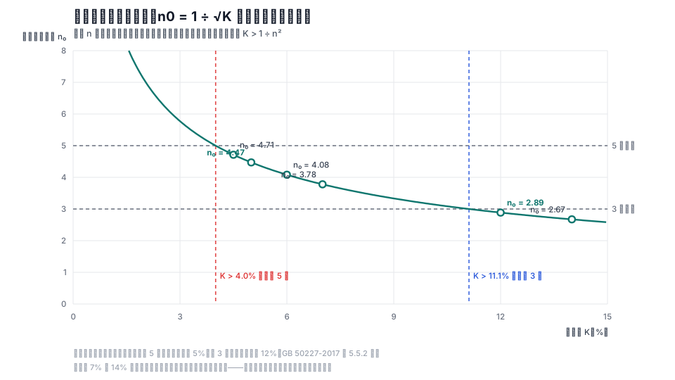
These two values are not arbitrary; they can be checked from the branch's own resonance point. For a branch with detuning factor K, the series resonance order is n0 = 1 ÷ √K. To keep a given harmonic outside the capacitive region, n0 must be lower than that harmonic, meaning K > 1 ÷ n²:
| Lowest harmonic to avoid | Threshold K > 1 ÷ n² | Standard rating | Rating margin over threshold |
|---|---|---|---|
| 5th | 4.0% | 5% | 1.25 times |
| 3rd | 11.1% | 12% | 1.08 times |
The branch resonance points for each rating are:
| K | 4.5% | 5% | 6% | 7% | 12% | 14% |
|---|---|---|---|---|---|---|
| n0 = 1 ÷ √K | 4.7140 | 4.4721 | 4.0825 | 3.7796 | 2.8868 | 2.6726 |
The explanatory text of GB 50052-2009, Clause 6.0.13, gives a finer basis: when fifth-harmonic voltage is high and third-harmonic voltage is not, K should be 4.5%; when third-harmonic voltage is high, 12% is recommended; when harmonic voltage is low, 0.5% is recommended.
The commonly used 7% and 14% values have n0 of 3.7796 and 2.6726, respectively, also below the thresholds. They are not wrong ratings; they provide a larger equivalent margin. The cost appears in the next section: the higher the detuning factor, the higher the terminal voltage and the greater the output reduction.
What is the cost of selecting the next higher voltage class?
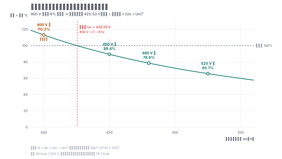
The reactive power output of a capacitor is proportional to the square of terminal voltage:
Q = Qn × (Uc ÷ Un)²
Qn is the rated capacity marked on the data sheet and calibrated at rated voltage Un (GB/T 22582-2023, Power Capacitors—Low-Voltage Power Factor Correction Equipment, defines it as "the reactive power that can be continuously output at rated voltage"). Uc is the actual operating terminal voltage. If the two voltages are not equal, output is not the nameplate value.
At a terminal voltage of 425.53 V (400 V bus + 6% reactor):
| Capacitor rated voltage | Output ÷ rated | Ordered capacity needed for 400 kvar actual output |
|---|---|---|
| 450 V class | 89.4% | 447.3 kvar |
| 480 V class | 78.6% | 509.0 kvar |
| 525 V class | 65.7% | 608.9 kvar |
A 30 kvar / 525 V capacitor installed here actually produces only 19.7 kvar.
"Insufficient compensation-cabinet capacity" often has the cause in this table: the ordered rating is being used as the output, while the actual output has been reduced. Conversely, a lower rated voltage produces sufficient output—a 400 V-class unit produces 113.2%—but that is overvoltage operation, not margin.
The voltage class is therefore not safer simply because it is higher. It is a conversion that trades capacity for insulation margin. Before selecting it, calculate at least two things: how high terminal voltage will rise, and what percentage of output remains at that voltage.
How can grouped switching be checked to avoid resonance?
GB 50052-2009, Clause 6.0.11, on "capacitor grouping," requires that grouped capacitors must not produce resonance when switched, and that the number of groups should be appropriately reduced while group capacity is increased.
The parallel-resonance capacity can be derived. The capacitive reactance of the capacitor branch at the nth harmonic is Xc0 × (1 ÷ n − K × n), where Xc0 is fundamental-frequency capacitive reactance. The system-side inductive reactance is n × U² ÷ Sd, where Sd is the short-circuit capacity at the installation point. Setting the two equal for parallel resonance and substituting Xc0 = U² ÷ Qc gives:
Qcx = Sd × (1 − K × n²) ÷ n²
When K = 0, this reduces to Qcx = Sd ÷ n², the familiar rule that "compensation capacity equals short-circuit capacity divided by n²" at the nth-order resonance.
Test a 630 kVA transformer with 6% impedance voltage. Its low-voltage-side short-circuit capacity is approximately 0.63 ÷ 0.06 = 10.5 MVA.
- Without a reactor, at the fifth harmonic: Qcx = 10.5 ÷ 25 = 0.4200 Mvar = 420 kvar. If this transformer uses 400 kvar of compensation, it is only 4.8% away from the resonance point.
- With 6% detuning, at the fifth harmonic: 1 − 0.06 × 25 < 0, so there is no positive solution—the branch is already inductive at the fifth harmonic and fifth-order parallel resonance will not occur.
- With 6% detuning, at the third harmonic: 1 − 0.06 × 9 = 0.46, so Qcx = 10.5 × 0.46 ÷ 9 = 536.7 kvar. The fifth harmonic is avoided, but the third remains.
- With 12% detuning, at the third harmonic: 1 − 0.12 × 9 < 0, so there is no positive solution.
For the same formula on a 1,250 kVA transformer (short-circuit capacity approximately 20.8 MVA), the fifth-order resonance point without a reactor is 833.3 kvar.
That is why "measure background harmonics first" is not a formality. It determines which harmonic order must be avoided; that order determines the detuning factor; the detuning factor determines terminal voltage; and terminal voltage determines the rated voltage and how much capacity must be ordered. The chain begins with an on-site measurement.
Questions that still have no answer
- At what voltage is kvar on a data sheet actually calibrated? When a sheet says "30 kvar," does that mean capacity at rated voltage or output at the nominal system voltage? Manufacturers use different conventions and there is no uniform marking requirement, so each supplier must be asked. This article uses the former basis for its conversion.
- New projects may not have measured background-harmonic data and must estimate from similar projects. Underestimating it selects too small a detuning factor; overestimating means buying more capacitor capacity. There is currently no public universal table.
- The statement in the explanatory text of GB 50052-2009 that "most domestic manufacturers allow only 1.05 times for long-term operation" was recorded in 2009. No public statistics show how many manufacturers still use that basis today.
References
All links below were accessed on 2026-09-17.
- GB/T 156-2017, Standard Voltages (current; implemented on 2018-05-01, fully replacing GB/T 156-2007). https://std.samr.gov.cn/gb/search/gbDetailed?id=71F772D82246D3A7E05397BE0A0AB82A
- GB 50052-2009, Code for Design of Electric Power Supply and Distribution Systems, Clauses 5.0.4, 6.0.5, and 6.0.11 and the explanatory text of Chapter 6 (current). (No public link.)
- GB 50227-2017, Code for Design of Installations of Parallel Capacitors, Clause 5.5.2 (current). https://www.mohurd.gov.cn/gongkai/zc/wjk/art/2017/art_17339_232353.html
- GB/T 12747.1-2017, Self-healing Shunt Capacitors for AC Power Systems Having a Rated Voltage up to and Including 1,000 V—Part 1: General. https://std.samr.gov.cn/gb/search/gbDetailed?id=71F772D81ACED3A7E05397BE0A0AB82A
- GB/T 22582-2023, Power Capacitors—Low-Voltage Power Factor Correction Equipment. https://std.samr.gov.cn/gb/search/gbDetailed?id=FC816D05005E62EBE05397BE0A0AD5FA
- Ministry of Water Resources and Electric Power and State Price Bureau, Measures for Adjustment of Electricity Charges Based on Power Factor (1983, Water and Electricity Finance No. 215). https://95598.cn/omg-static//omg-static/99303161051039894503000660312033.pdf
- National Public Service Platform for Standards Information, std.samr.gov.cn (check of current status of standards). https://std.samr.gov.cn/
This article is an industry observation and does not constitute procurement advice.