
Conclusion
The demand factor method should be applied only once: apply each group's demand factor Kx to obtain its calculated load, add the groups and apply one coincidence factor, divide by the compensated power factor to obtain the calculated capacity, then work backwards from the requirement that the long-term load factor should not exceed 85% (GB 51348-2019, Clause 4.3.2), and move up to a standard capacity rating. Stop there.
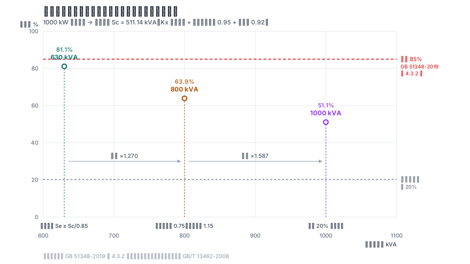
Many answers still "divide by the load factor" and then "add a 1.1–1.3 margin" after the calculation. Kx itself is a combined discount of "coincidence factor × load factor ÷ equipment efficiency ÷ line efficiency". The load factor used for capacity selection is a target, not another conversion factor. Using a 1,000 kW installed capacity as an example: a single conversion gives 630 kVA, two layers give 800 kVA, and three layers give 1,000 kVA—an increase of 1.27–1.59 times. The cost appears in investment and basic electricity charges; at the same load, the larger capacity can actually have lower losses.
Which standard should be used to select transformer capacity?
The most widely circulated formula is "transformer capacity = installed capacity × coincidence factor ÷ power factor ÷ load factor". Many pages attribute it to GB 50052-2009, Code for Design of Electric Power Supply and Distribution Systems, and some say that capacity should be set at 1.26 times the calculated load, corresponding to an 80% load factor. The table of contents tells a different story: the standard has seven chapters (general provisions, terms, load classification through reactive-power compensation, and low-voltage distribution), but no load-calculation chapter and no transformer-capacity chapter.
The two matters are actually governed by several other provisions:
| What to check | Source |
|---|---|
| Which method to use for load calculation | GB 51348-2019, Clause 3.5. §3.5.2: "At the preliminary-design and construction-drawing-design stages, the demand factor method should be used." |
| Transformer quantity and N-1 | GB 50053-2013, Section 3.3. §3.3.2: when any transformer is disconnected, the remaining transformers should meet all Class I and Class II loads |
| Long-term load-factor limit | GB 51348-2019, Clause 4.3.2: should not exceed 85% |
| Upper limit for a single-unit capacity | GB 50053-2013, §3.3.3: the 0.4 kV side of a substation should not exceed 1,250 kVA; GB 51348-2019, §4.3.7: for civil buildings, it should not exceed 2,000 kVA, and when there is only one unit it should not exceed 1,250 kVA |
The last two limits look contradictory, but one applies to substations and the other to civil buildings.
What is actually included in demand factor Kx?
The demand factor is not simply a discount for "equipment not operating at the same time". It is a combination of four factors:
Kx = (KΣ · K_L) / (η_e · η_WL)
KΣ is the coincidence factor, K_L is the load factor, η_e is the average efficiency of the equipment group, and η_WL is the average efficiency of the distribution line (generally 0.95–0.98). This formula appears in the Design Manual for Industrial and Civil Power Distribution and university textbooks; Zhang Li gives the same form in Electrical Technology for Intelligent Buildings, Issue 6, 2022.
Equipment selection already contains safety factors—fans often carry an additional factor of 1.13–1.5, pumps 1.05–1.7, and specifications are normally selected upward rather than downward. Zhang's result is that the load factor can be taken as the inverse of the safety factor: 0.59–0.95 for pumps and 0.67–0.89 for fans. He also states directly: "The demand factor comes from load surveys and measurements; the calculation indicators and factors listed in common manuals are usually on the high side."
That is why Kx for equipment groups in one manual table ranges from 0.12 to 0.90. Kx has already been applied once.
After calculating the load, should the result be divided by the load factor again?
This is the central issue. The two quantities called "load factor" have different meanings:
| Name | Definition | Where it appears |
|---|---|---|
| Load factor K_L | Actual power required by operating equipment ÷ total power of operating equipment | Included in Kx |
| Load factor β | Calculated capacity Sc ÷ rated transformer capacity Se | Used for capacity selection |
When selecting capacity, the load factor is a threshold, not a reduction: keep Sc/Se at or below 85%, meaning Se ≥ Sc/0.85. This step is already a "load-factor conversion". Dividing by a load factor again uses it twice.
A widely circulated example is a 500 kW equipment installation, using a coincidence factor of 0.7, a power factor of 0.85, and a load factor of 0.7: 588 kVA, then 630 kVA selected. Under the "single conversion" check, 350 kW is already the calculated active load, and 350/0.85 = 412 kVA is already the calculated capacity. Dividing by 0.85 again gives 485 kVA, so 500 kVA would be selected—one rating lower.
One qualification is necessary: if the original meaning of 0.7 was "use a target utilization rate to work backwards from capacity," rather than "discount the load," the basis is different and it is not a duplicate conversion.
There is also a separate case: utility-connection applications are not calculated this way. Some local power-supply authorities explicitly include an "economic operation factor for the distribution transformer" in their connection-capacity formula (one city's 2020 rule uses 0.7) and require compensation capacity to be 40% of transformer capacity. That basis describes "how much capacity to apply for with the utility," not "how large a transformer to purchase." Mixing the two is what causes errors.
At which level should the coincidence factor be applied?
Coincidence factors exist at every level—within equipment groups, on distribution feeders, and in the transformer room. The correct approach is to apply them by level, not once at the final circuit and again at the transformer. Zhang gives a three-level distribution example: three factors of 0.8 × 0.9 × 0.9 are multiplied successively, leaving a demand factor of only 0.65 on the transformer low-voltage side. Some drawings uniformly use 0.8 at a building's incoming line; he points out that this is "too high."
Calculation: what capacity should be selected for a 1,000 kW installed load?
There are three equipment groups. Kx uses the upper end of the manual's range and cosφ uses the lower end—both sides are deliberately conservative:
| Equipment group | Installed capacity ΣPe | Kx | cosφ | Pc = Kx·ΣPe | Qc = Pc·tanφ |
|---|---|---|---|---|---|
| Small-batch metal cold-working machine tools | 500 kW | 0.16 | 0.50 | 80.00 kW | 138.56 kvar |
| Production ventilation fans | 300 kW | 0.85 | 0.80 | 255.00 kW | 191.25 kvar |
| Pumps, piston compressors, and air-conditioning supply fans | 200 kW | 0.80 | 0.80 | 160.00 kW | 120.00 kvar |
| Total | 1000 kW | — | — | 495.00 kW | 449.81 kvar |
The group coincidence factor of 0.95 is applied once: Pc = 470.25 kW, Qc = 427.32 kvar, pre-compensation power factor 0.740, Sc = 635.41 kVA.
Compensating to 0.92 (GB 51348-2019, Clause 3.6.4, requires the power factor at the metering point to generally be no lower than 0.9) requires 227.00 kvar, giving Sc = 511.14 kVA. The calculated capacity is fixed at this point. There are two possible paths:
| Method | Calculation | Result | Long-term load factor |
|---|---|---|---|
| Single conversion (correct method) | 511.14 / 0.85 = 601.34 kVA, move up a rating | 630 kVA | 81.1% |
| Divide again by a target load factor of 0.75, then add a 1.15 margin | 511.14 / 0.75 × 1.15 = 783.75 kVA | 800 kVA (×1.270) | 63.9% |
| Add another 20% expansion margin | 511.14 / 0.75 × 1.20 = 817.83 kVA | 1000 kVA (×1.587) | 51.1% |
For the same load, capacity differs by 1.27–1.59 times and the long-term load factor falls from 81.1% to 51.1%.
Does selecting the next larger capacity really increase energy use?
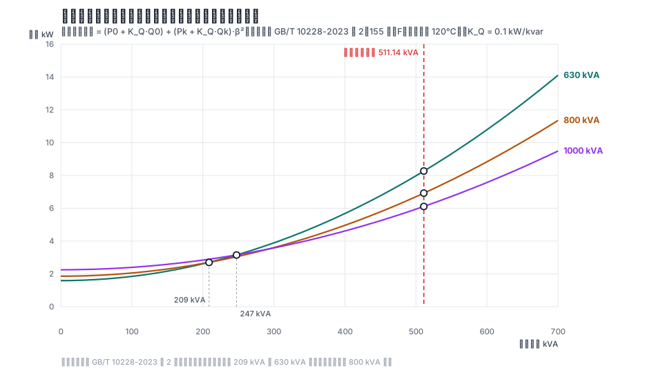
That is the intuitive answer. According to Table 2 of GB/T 10228-2023 (10 kV class, off-circuit tap changing; load losses use the 155 class/F, reference-temperature 120°C column), the no-load and load losses of 630/800/1,000 kVA units are 1.15/6.36, 1.30/7.60, and 1.55/8.78 kW. The 2023 edition reduces average no-load loss by about 20% while leaving load loss unchanged; using figures from the 2015 edition would overestimate core loss. Connect the same 511.14 kVA load:
| Capacity | Load factor β | Core loss | Copper loss = Pk·β² | Total active-power loss | Overall power loss |
|---|---|---|---|---|---|
| 630 kVA | 81.1% | 1.15 kW | 4.187 kW | 5.34 kW | 8.27 kW |
| 800 kVA | 63.9% | 1.30 kW | 3.103 kW | 4.40 kW | 6.92 kW |
| 1000 kVA | 51.1% | 1.55 kW | 2.294 kW | 3.84 kW | 6.11 kW |
Core loss increases only slightly, while copper loss falls with the square of the load factor. At the same load, the next larger capacity actually has lower total losses. The difference in overall power loss between 630 and 800 is 1.344 kW, or about 12,000 kWh per year. Between 630 and 1,000 it is 2.154 kW, or about 19,000 kWh per year.
When does choosing larger become a loss? Solve for the intersection of the two loss curves. Below 209 kVA, 630 kVA saves more than 800 kVA; below 247 kVA, 630 kVA saves more than 1,000 kVA—equivalent to 40.8% and 48.4% of the calculated load in this example. Under GB/T 13462-2008, the lower boundary of the optimum economic operating range for the three capacities is 20.0%–20.9%, with an upper boundary of 75%; the 51.1% and 63.9% results from repeated conversion are still within the range.
Therefore, the cost of repeated conversion is not the transformer's own energy use, but three other things: equipment investment; a larger basic electricity charge when it is billed by transformer capacity; and reactive-power compensation and low-voltage-side equipment sized in proportion to capacity.
The intersection itself has a boundary: it changes with the overall power basis. If only active-power loss is counted, the intersections are 190 kVA and 235 kVA. Including the reactive-power economic equivalent at 0.1 kW/kvar gives 209 kVA and 247 kVA. The higher the reactive-power economic equivalent, the larger the intersection and the narrower the load range in which "larger is more efficient."
How should Kx be selected? Manual values and online answers can differ by a factor of two
The same manual table gives Kx ranges of 0.12–0.16 for small-batch metal cold-working machine tools, 0.75–0.85 for ventilation fans, and 0.85–0.90 for refrigeration units. The lowest and highest values differ by nearly six times. Online "rule-of-thumb" values often give only a broad range: 0.2–0.35 is common for machining workshops.
The size of the gap is clear from one calculation: for an 800 kW installed capacity of cold-working machine tools, Kx = 0.16 at the upper end of the manual range gives a calculated capacity of 139.1 kVA and a selected 200 kVA unit; Kx = 0.35 gives 304.3 kVA and a selected 400 kVA unit. That is a full capacity rating apart, or 2.0 times.
When stating Kx, at least three points must be made clear: whether the upper or lower end of the range is used; the equipment count and duty cycle (equipment with intermittent duty must first be converted to a common duty basis); and whether the table already includes the load factor.
For only one or two items of a similar type, Kx should use the upper end of the range, or even 1.0.
Questions that still have no answer
- A uniform Kx table: manuals and design atlases give different ranges for the same equipment class, and local utility-connection formulas also differ (whether they include an "economic operation factor" and what value they use). There is no version that can be applied nationwide without review.
- Demand factors for new civil-building loads: multi-split systems, ground-source and water-source heat pumps, LED displays, IT equipment, and hot-water dispensers are major loads for which public manuals generally provide no clear values.
Other common questions
Is the 85% limit alone enough for capacity selection? No. The second half of GB 51348-2019, Clause 4.3.2, also says that when Class I or Class II loads exist, two or more transformers should preferably be installed, and when one is out of service the remaining transformers should meet all Class I and Class II loads (also stated in GB 50053-2013, §3.3.2). This constrains transformer quantity and individual-unit capacity.
Can the demand factor method be used for small circuits? No. Zhang states explicitly in the same article that it does not apply to low-voltage final circuits, and is intended only for high-voltage distribution systems, low-voltage busbars, and low-voltage distribution lines.
References
All links below were accessed on 2026-09-16.
- GB 51348-2019, Standard for Electrical Design of Civil Buildings, Clauses 3.5, 3.6.4, 4.3.2, and 4.3.7. https://www.mohurd.gov.cn/gongkai/zc/wjk/art/2020/art_17339_247248.html
- GB 50053-2013, Code for Design of Substations of 20 kV and Below, Section 3.3. https://www.mohurd.gov.cn/gongkai/zc/wjk/art/2015/art_17339_224959.html
- GB 50052-2009, Code for Design of Electric Power Supply and Distribution Systems (this article checks that it contains no load-calculation or transformer-capacity chapter). (No public link.)
- GB/T 10228-2023, Specification and Technical Requirements for Dry-Type Power Transformers, Table 2, and GB/T 13462-2008, Economic Operation of Power Transformers. https://std.samr.gov.cn/gb/search/gbDetailed?id=FC816D05005D62EBE05397BE0A0AD5FA | https://openstd.samr.gov.cn/bzgk/gb/newGbInfo?hcno=CFE3F43386EC606D024BD0DDBC42CB8F
- Design Manual for Industrial and Civil Power Distribution, demand-factor table for common electrical equipment. (No public link.)
- Zhang Li. "Discussion on the Application of the Demand Factor Method." Electrical Technology for Intelligent Buildings, 2022, 16(06): 85–89. (No public link.)
- Jiangmen Municipal Development and Reform Bureau, Regulations on the Construction and Management of Power-Supply Facilities for Large Public Places and Commercial-Residential Complexes (2020). https://www.jiangmen.gov.cn/newzwgk/zfgb/zfgb2020nd2q/bmgfxwjxd/content/post_2127886.html
Updated 2026-09. This article is an industry observation and does not constitute procurement advice.