
Conclusion
The current code does not give a specific size for either item. For transformer-room ventilation, it gives three temperatures: exhaust air no higher than 45°C, the exhaust-to-intake temperature difference no higher than 15°C, and ambient temperature no higher than 40°C. Airflow must be calculated from heat balance; each 1 kW of loss requires approximately 199 m³/h. Once intake air exceeds 30°C, the controlling condition changes to "exhaust air no higher than 45°C," and required airflow can increase by up to 3.00 times. An oil pit is sized as a proportion of transformer-oil quantity: an oil-retaining pit of no less than 20% is allowed in general locations, while locations named by the code must use 100%. 1,000 kg of oil is approximately 1.12–1.20 m³.
What does the code actually require for transformer-room ventilation?
Clause 6.3.1 of Code for Design of Substations of 20 kV and Below, GB 50053-2013, contains only two sentences: "Transformer rooms should preferably use natural ventilation. In summer, exhaust-air temperature should not be higher than 45°C, and the temperature difference between exhaust and intake air should not be greater than 15°C. When natural ventilation cannot meet the requirements, mechanical ventilation should be added."
The explanatory text adds a third condition: these values were "determined from many years of domestic experience," and design should use exhaust air no higher than 45°C, a temperature difference no greater than 15°C, and ambient temperature no higher than 40°C.
All three are temperatures. Across all five clauses in Section 6.3 and their explanatory texts, there is no air velocity, window area, or air-change rate. This gap is not an omission: dimensions are the result of temperature, heat-transfer, and outdoor-weather calculations, and fixing them as universal values would necessarily fail for some projects. Of the ten mandatory provisions identified in Announcement No. 268, none belongs to Section 6.3; Clause 6.1.4, "ventilation windows shall use non-combustible materials," is also not included.
Why does the same transformer need several times more airflow when intake temperature rises?
Exhaust temperature equals intake temperature plus the exhaust-to-intake temperature difference. Both upper limits apply, so the permitted difference is the tighter of the two:
Δt = min(15°C, 45°C − intake temperature)
| Summer intake temperature | Permitted difference Δt | Controlling condition | Airflow required per 1 kW loss | Relative to baseline |
|---|---|---|---|---|
| 25°C | 15°C | Temperature difference no greater than 15°C | 199.0 m³/h | 1.00 times |
| 30°C | 15°C | Temperature difference no greater than 15°C | 199.0 m³/h | 1.00 times |
| 32°C | 13°C | Exhaust air no higher than 45°C | 229.6 m³/h | 1.15 times |
| 35°C | 10°C | Exhaust air no higher than 45°C | 298.5 m³/h | 1.50 times |
| 40°C | 5°C | Exhaust air no higher than 45°C | 597.0 m³/h | 3.00 times |
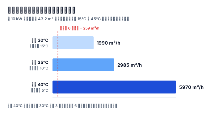
The boundary is 30°C. At 30°C and below, the controlling condition is a temperature difference of no more than 15°C. Above 30°C, "exhaust air no higher than 45°C" takes over, and airflow increases by 15 ÷ (45 − intake temperature). For the same room and transformer, required airflow at 40°C intake is 3.00 times that at 30°C.
At 40°C intake, all three temperature conditions are already at their boundaries. Above that, mechanical ventilation or intake cooling is required—the premise "ambient temperature no higher than 40°C" has itself been exceeded. Ventilation is therefore calculated for the most unfavorable summer intake temperature, not the annual average.
How is airflow calculated, and how much is needed per 1 kW of loss?
Heat carried away by ventilation should equal transformer loss. Write it as:
L = Q ÷ (ρ × c × Δt)
L is airflow, Q is loss, ρ is air density, and c is the specific heat of air at constant pressure. Taking ρ = 1.2 kg/m³ and c = 1005 J/(kg·K), 1 kW requires 199.0 m³/h at a 15°C difference, 298.5 m³/h at 10°C, and 597.0 m³/h at 5°C.
Put this into a room measuring 4.0 m × 3.0 m × 3.6 m, with a volume of 43.2 m³:
| Transformer loss | Required airflow (15°C difference) |
|---|---|
| 5 kW | 995 m³/h |
| 10 kW | 1990 m³/h |
| 15 kW | 2985 m³/h |
Q is the sum of no-load and load loss of the selected transformer and changes with load factor. The same transformer room therefore needs different airflow at light and full load, while none of the code's three temperature conditions changes.
The effect of constant selection can be calculated. Changing specific heat to the engineering value of 1.01 kJ/(kg·K) changes the requirement from 199.0 to 198.0 m³/h per kW, a 0.5% difference. Recalculating with an air density of 1.11 kg/m³ at 45°C exhaust gives 215.1 m³/h, 8.1% higher. Neither changes the order of magnitude.
Where do "inlet-window area not less than 1/20" and "six air changes per hour" come from?
As of 2026-09, two publicly available technical documents located by this article say different things: one says that under natural ventilation, inlet-window area should be at least 1/20 of the transformer heat-dissipation area; the other says that the natural ventilation opening should not be less than 5% of transformer-room floor area and that the air-change rate should be at least six per hour. Both attach these statements to GB 50053.
Three points can be checked directly. First, the area bases differ—one uses heat-dissipation area and the other floor area—so they cannot be converted into each other. Second, Section 6.3 contains neither an area ratio nor an air-change rate. Third, the same material also says that airflow should be at least 0.28 m³/s per kW of loss. Reversing that using the 45°C and 15°C values it cites implies a permitted temperature difference of only 2.96°C, about five times stricter than 15°C.
Air-change rate is not a wrong tool; it is another way to express heat removal. Writing it as a fixed number treats loss as constant. For the 43.2 m³ room above, six air changes per hour is 259.2 m³/h, which can remove only 1.30 kW at a 15°C difference. Conversely, 10 kW requires 1990 m³/h, or 46.1 air changes per hour in this room—7.7 times six. Whether the answer is six or 46 depends on the quantity that was not written down: how many kilowatts this transformer loses.
Why cannot a capacitor room use the transformer-room rule?
Clause 6.3.2 uses a different basis: "A capacitor room should have good natural ventilation. Airflow should be calculated according to the temperature permitted for the capacitor, with summer exhaust temperature no higher than the maximum permitted ambient-air temperature of the capacitor. When natural ventilation cannot meet the requirements, mechanical ventilation may be added."
The difference is where the upper limit comes from. The transformer-room limit of 45°C is written in the code. The capacitor-room limit is not in the code; it is written in the capacitor product's temperature category.
| Maximum permitted ambient-air temperature for capacitor | Permitted difference at 35°C intake | Airflow required per 1 kW loss |
|---|---|---|
| 45°C | 10°C | 298.5 m³/h |
| 50°C | 15°C | 199.0 m³/h |
| 55°C | 20°C | 149.3 m³/h |
This is also why capacitor-room airflow is difficult to calculate at the drawing stage: the numerator, total loss, is not known until the capacitors are selected. The explanatory text specifically warns that the maximum ambient temperature and 24-hour average maximum temperature should be considered during selection.
Should the oil pit contain 100% or 20% of the transformer oil?
Both values are correct, depending on the location. Clause 6.1.6 (a mandatory provision) requires an oil pit with capacity equal to 100% of the transformer oil for oil-immersed transformer rooms in podiums of high-rise buildings, attached substations in multi-story buildings, and substations inside workshops. Clause 6.1.7 (also mandatory) gives the general rule first: when an oil-retaining pit with capacity of no less than 20% of the oil quantity is provided, there must be a facility to drain the oil to a safe location. It then names three types of location that still require 100%: places where combustible dust or fibers can accumulate; open locations nearby with large concentrations of flammable materials such as grain or cotton; and cases where there is a basement below the oil-immersed transformer room. Clause 6.1.8 adds a threshold by oil quantity: in independent substations, attached substations, and outdoor or semi-outdoor substations, an oil-immersed transformer with oil quantity of at least 1,000 kg must have an oil pit or oil-retaining pit.
Therefore, 100% and 20% are not two mutually exclusive choices; they are two criteria—"look at the location" and "look at the oil quantity." A general location may use a 20% oil-retaining pit together with a facility that drains oil to a safe place; a named location has no such option. Some references merge the rules into "more than 1,000 kg of oil requires 100% design" and omit the location criterion.
The conversion basis appears in the explanatory text of Clause 6.1.5: for transformers of 1,250 kVA and below, oil quantity is 1,000 kg and below; for 1,600–6,300 kVA, it is in the range of 1,000–2,500 kg. It also says that "when implementing this clause, the actual transformer oil quantity must be checked." The 1,250 kVA rating is right at the 1,000 kg boundary, which explains why the adjacent Clause 6.1.8 uses 1,000 kg as its threshold.
How many cubic metres is 1,000 kg of oil, and can a 250 mm pebble layer contain it?
Take transformer-oil density as 0.83–0.895 t/m³. 1,000 kg of oil is approximately 1.12–1.20 m³; 20% of the oil quantity is 200 kg, or about 0.223 m³.
The explanatory text of Clause 6.1.6 gives the usual practice: "The usual practice for an oil pit is to fill the transformer oil trench with a pebble layer thicker than 250 mm, install an oil pit under the pebble layer, or use the voids between the pebbles in the transformer oil trench."
The second option is worth calculating. If the voids between pebbles are used, a 250 mm layer with an estimated void ratio of 0.35–0.45 can hold 0.0875–0.1125 m³ of oil per square metre of pit area. Containing 1,000 kg of oil requires a pit area of 9.9–13.8 m², or approximately 11.2 m² at a void ratio of 0.40. Most transformer rooms cannot spare an oil-pit area on the scale of ten square metres. This is why the explanatory text lists "an oil pit under the pebble layer" as the usual practice, and why 250 mm should not be read as an oil-volume requirement: it concerns separation from an oil fire and heat dissipation.
Questions that still have no answer
After calculating airflow, how many square metres of window can pass it? There is no universal conversion table. It depends on the height difference between intake and exhaust openings, opening form, resistance from louvers and insect screens, and outdoor wind speed and direction. As of 2026-09, the public sources searched for this article did not provide a directly usable conversion basis.
At what load factor should airflow be calculated? The code does not specify it. Full-load calculation is safe but may make the window too large.
There is no code value for pebble-layer void ratio. The assumed 0.35–0.45 affects pit area by tens of percent but does not change the order-of-magnitude conclusion of "about ten square metres."
References
- Ministry of Housing and Urban-Rural Development of the People's Republic of China, Announcement No. 268, Announcement on Issuing the National Standard Code for Design of Substations of 20 kV and Below, 2013-12-19. https://www.mohurd.gov.cn/gongkai/zc/wjk/art/2015/art_17339_224959.html (accessed 2026-09-17)
- GB 50053-2013, Code for Design of Substations of 20 kV and Below, full text issued on the Ministry of Housing and Urban-Rural Development website. https://www.mohurd.gov.cn/file/old/2013/20131230/GB50053-201320KV%E5%8F%8A%E4%BB%A5%E4%B8%8B%E5%8F%98%E7%94%B5%E6%89%80%E8%AE%BE%E8%AE%A1%E8%A7%84%E8%8C%83.pdf (accessed 2026-09-17)
- GB 50053-2013, Section 6.1, "Fire Protection," and Section 6.3, "Heating and Ventilation," clauses and explanatory text. https://ixiaofang.com/10489.html (accessed 2026-09-17)
- Sinopec transformer-oil product data sheet (typical density at 20°C of 831.0–833.6 kg/m³; standard limit 895 kg/m³). http://sinolubesg.sinopec.com/sinolubesg/Resource/pdf/Type%20U%20Insulated%20Transformer%20Oil.pdf (accessed 2026-09-17)
- Conditions Required for an Oil-Immersed Transformer Room (third-party technical material, source of two statements in the fourth question). https://b2bwiki.aipage.com/article/d1ogeg1ftjsppaq1n3bg (accessed 2026-09-17)
- Design Requirements and Technical Measures for Transformer-Room Fire Protection (third-party technical material, source of two statements in the fourth question). https://renrendoc.com/paper/508937178.html (accessed 2026-09-17)
This article is an industry observation and does not constitute procurement advice. | Updated 2026-09