
Conclusion
Yes, it will—and the first wave of changes is already visible. What is being removed is the low-voltage AC busway, replaced by an 800 V DC busway. More importantly, based on the forecast from third-party research firm SemiAnalysis, early DC busways may be designed as feeder-only systems that deliver power but do not provide tap-off connections. One widely repeated interpretation also needs correcting: in NVIDIA's figures, the claim that "copper is reduced by 45%" uses 415 V AC distribution as its baseline, not the 54 V busway inside the rack.
What is actually different between an 800 V DC busway and today's AC busway?
The differences concentrate in three areas: conductor count, conductor-to-ground voltage, and interruption method.
Conductor count is the easiest to see, and the least important: today's data-center busway uses three-phase, four-wire distribution (three phases + N) plus PE, while 800 V DC uses two conductors (positive + return), with PE normally still provided separately.
The conductor-to-ground voltage needs a clarification because two concepts are often mixed together in Chinese-language material: single-pole +800 V and bipolar ±400 V are two parallel routes, not the same thing. NVIDIA's Kyber architecture uses single-pole +800 V and two conductors. OCP's Diablo 400 route uses bipolar ±400 V and three conductors (+400 V / 0 V / −400 V), jointly signed by Google, Meta, and Microsoft and published as draft v0.5.2 in May 2025, then revised to v0.7.0. The maximum conductor-to-ground voltage differs between the two routes (800 V versus 400 V), so their insulation thickness and creepage-distance requirements also differ. Some Chinese material says that "800 V HVDC mainly uses a ±400 V bipolar busway"; that merges two routes into one and can lead to an incorrect selection.
The third difference is what really determines the form factor: interruption. AC crosses zero once every half-cycle, allowing the arc to extinguish by itself. DC has no zero crossing, so an arc produced during interruption under load continues to discharge rather than extinguishing on its own. This directly determines the form of DC circuit breakers and tap-off units.
With the same 1 MW, how much thinner can an 800 V DC busway be than a 54 V busway?
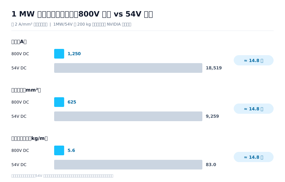
Start with the most direct comparison. Take 1 MW, which is in the range of a megawatt-scale AI rack (according to NVIDIA's public rack-power roadmap, the target for a native 800 V Gen4 architecture is close to 1 MW per rack).
- At 800 V DC: I = P ÷ U = 1,000,000 ÷ 800 = 1,250 A
- At 54 V DC: I = 1,000,000 ÷ 54 ≈ 18,519 A
- The difference is approximately 14.8 times (800 ÷ 54)
This ratio is not an estimate; it can be checked against an anchor point supplied by NVIDIA itself. A technical blog states that if a 1 MW rack continued to use 54 V DC, the busbars inside the rack alone could require up to 200 kg of copper. Working backwards: at a copper density of 8.96 g/cm³, 200 kg of copper occupies 22,321 cm³. At a typical busbar current density of about 2 A/mm², 18,519 A requires a conductor cross-section of 9,259 mm² (about 92.6 cm²). Then 22,321 ÷ 92.6 ≈ 241 cm. In other words, those 200 kg correspond to about 2.4 m of busbar—entirely plausible inside a megawatt-scale rack. This shows that 200 kg is calculated, not advertised.
The resulting order-of-magnitude conclusion is the same: at the same 1 MW and the same current density, 800 V DC needs a conductor cross-section of about one-fifteenth that of 54 V DC (about 625 mm² versus 9,259 mm²).
The condition is that current density and cooling conditions are the same on both sides. Actual engineering also needs to consider installation method, ambient temperature, forced-air cooling, and the need to increase both cross-sections for long runs or high ambient temperatures—but the ratio between the two remains broadly unchanged. (Scope: low-voltage DC busways inside racks are nominally available in both 48 V and 54 V forms; the former is associated with the OCP system and the latter is NVIDIA's current terminology. This article consistently uses 54 V.)
What is the baseline for NVIDIA's "45% less copper" claim?
It is 415 V AC distribution. Both statements come from NVIDIA's official material and use this baseline, but they are worth reading together.
NVIDIA has given two figures for the same topic. A technical blog from May 2025 says that using an 800 V busway in distribution and replacing 415 V AC with 800 V DC can transmit 85% more power at the same conductor cross-section. A white paper, 800 VDC Architecture for Next-Generation AI Infrastructure, and a blog revision from October of the same year instead say that the power transmitted with the same wire gauge is 157% higher than with 415 V AC. Both figures are tied to the 415 V AC baseline, but they differ substantially.
The difference lies in the conversion basis, which only the latter states explicitly. Table 1 of the white paper gives the power that can be transmitted per square millimeter of cable cross-section: 0.6 kW/mm² for four 415 V AC conductors (P1/P2/P3/PE); 0.8 kW/mm² for four 480 V AC conductors; 1.7 kW/mm² for three 800 V DC conductors (POS/RTN/PE), marked +157%; and 3.1 kW/mm² for three 1,500 V DC conductors, marked +382%. The 157% contains two effects—higher voltage and a reduction from four conductors to three. If converted only by voltage ratio, 800 ÷ 415 is about +93%, which does not reach 157%. The 85% version does not disclose its conversion basis, so it cannot be derived from the voltage ratio or from the white paper's basis; it can only be treated as an order-of-magnitude description.
Two additional cautions follow. First, the percentages printed in Table 1 do not recalculate from the printed values: 0.8 relative to 0.6 is +33% (the table lists +16%), 1.7 relative to 0.6 is +183% (the table lists +157%), and 3.1 relative to 0.6 is +417% (the table lists +382%). All three rows only work if approximately 0.65 kW/mm² is used as the 415 V baseline. When citing the table, use values from the same document consistently. Second, NVIDIA's Chinese site translates the figure in the same blog as "15.7% higher," while the English original says 157%; quoting the Chinese version changes the order of magnitude.
Now to the 45%. The original wording is "45% less copper demand than a traditional 415 V AC architecture." The key qualifier is electrical distribution—it refers to the facility-side section downstream of the transformer, not the busbar inside the rack. In Chinese retellings, the baseline is often omitted, making the claim sound like "800 V uses 45% less copper than the current 54 V rack busbar." Those are entirely different comparisons. The two figures serve different purposes:
| Figure | Comparison | What it describes |
|---|---|---|
| Approx. 14.8 times (current ratio) | 54 V DC busway inside a rack → 800 V DC | The order-of-magnitude difference in current and conductor cross-section in the rack section |
| 45% copper reduction | Facility-level 415 V AC distribution → 800 V DC | The total copper reduction in the "AC distribution" section of the chain |
This misreading is not hypothetical. A European industry publication described the figure as a copper reduction in "rack connectivity" (Cloudmagazin, 2026-06-17), while the original text refers to electrical distribution. The same number is being applied to two interpretations that differ by an entire rack section.
Why is the overall figure only 45% when the rack section differs by 15 times? Because not all the copper is in that section. SemiAnalysis's breakdown of data-center power architecture gives a clear boundary for 800 V DC: everything above the AC-to-DC conversion point is retained; everything below it that belongs to the AC distribution design is removed. The medium-voltage transformer connected to the grid, the medium-voltage switchgear, and the low-voltage transformer that steps down to 415 V remain largely unchanged. What is removed is the section below the 480 V AC switchgear (listed item by item below). A large amount of unchanged copper remains in the denominator, so the overall reduction is diluted to 45%.
(415 V and 480 V are regional designations at the same voltage level: the IEC system uses 415 V, while North America uses 480 V.)
Both figures can be correct, but only when tied to their own baseline. Using 45% to estimate the saving in the rack busbar will seriously underestimate it; using 15 times to estimate the copper saving for the entire site will seriously overestimate it. When a claim says that copper is reduced "by dozens of percent," the first question should be: reduced compared with what? The one condition here is that the 45% denominator excludes the rack section. If it actually includes the rack section, the interpretation that the rack section is understated would not hold.
Why can't early DC busways use tap-off units?
Because "plugging in and unplugging under load" is much harder in DC.
The modular tap-off units of AC busway can be installed and removed while energized because the AC arc extinguishes at each zero crossing. DC has no zero crossing, so the continuous arc produced when interrupting under load does not extinguish by itself. At 800 V, the arc energy is higher, and erosion of contacts and enclosures is more severe. A DC-specific tap-off unit must be larger to extinguish the arc, and is not yet practical for current engineering applications.
SemiAnalysis's 2026 800 VDC report gives a specific forecast: "We expect early 800 VDC deployments to use feeder-only busway, because tap-off becomes more complicated ... In addition, DC-rated tap-off units with sufficient arc-extinguishing capability are larger and not currently practical." A feeder-only busway has connections at both ends or at fixed points, without intermediate plug-in interfaces. Under this forecast, the first generation of 800 V DC busways will lose the "plug in anywhere" function that is most valued in AC busway. The same report also says that Delta and ABB have publicly disclosed 800 VDC busway projects, with Legrand, EAE, and others expected to follow in 2026.
An alternative route is already taking shape: use solid-state circuit breakers (SSCBs) for electronic interruption, avoiding the arc-extinguishing problem of mechanical contacts. NVIDIA's White Paper 2.0 lists SSCBs as a capability needed in the near term. Delta's publicly disclosed e-Fuse module uses SiC switches and has a stated fault-clearing time of less than 3 μs (manufacturer's specification).
Direct engineering impact: if a data center reserves space according to the AC-busway model—one tap-off point every certain distance, with capacity added later as needed—the design needs to be redone for a DC scheme. Condition under which this forecast fails: if dedicated DC tap-off units are deployed and validated in 2027–2028, this limitation will be removed and plug-in DC busways may return.
Are there standards for 800 V DC busways?
There are current standards that can be used; the common claim that there are none is incorrect.
According to the National Public Service Platform for Standards Information, the current GB/T 7251.6-2015, Low-voltage switchgear and controlgear assemblies—Part 6: Busbar trunking systems, is identical to IEC 61439-6:2012. It was published on 2015-05-15, implemented on 2016-06-01, and converted to a recommended standard from 2017-03-23. Its scope explicitly includes busbar trunking systems with a rated voltage not exceeding 1,000 V AC or 1,500 V DC. By voltage level alone, an 800 V DC busway is already within scope; there is no absence of a standard. The standard is being revised to adopt IEC 61439-6:2026 identically, with a public-comment period from 2026-07-27 to 2026-08-26.
The real bottleneck is not the voltage level, but the certification and verification route. NVIDIA's White Paper 2.0 states: "The current strategy is not to create an entirely new set of standards, but to leverage existing certification frameworks where feasible while identifying targeted updates needed to support emerging 800 V DC equipment and deployment architectures." It also states that NVIDIA is working with UL Solutions, OEMs, and data-center operators on this route.
A third-party discussion is even more direct. At the 2026 PCIM Europe roundtable on data-center power-distribution evolution, participants from Infineon, Renesas, STMicroelectronics, and Navitas shared the view that hyperscalers are moving ahead while safety standards and ecosystem readiness are lagging. OCP's Diablo 400 reference specification was still a draft in 2026, which reinforces the point.
The engineering meaning is one sentence: existing standards can be used for selection, but the verification items specific to DC do not yet have a clear common basis.
Which busways disappear, and which ones are added?
Break the chain apart and the change is "one section disappears, one section is new, and the upstream section stays":
| Link section | Under 800 V DC |
|---|---|
| Medium-voltage transformer and medium-voltage switchgear | Retained (the grid incoming supply is still AC) |
| Low-voltage transformer (stepping down to 415 V AC) | Route-dependent: retained for existing-site retrofits and transition schemes; replaced by a solid-state transformer in the next-generation route |
| 480 V AC switchgear | Removed |
| Low-voltage AC busway and floor PDU | Removed |
| Row-level / hall-level 800 V DC busway | Added (DC distribution after rectification) |
| 54 V busbar and power shelves inside the rack | Removed and replaced by rack-side DC/DC |
| DC tap-off unit | Added later (feeder-only in the early stage; see the previous section) |
| DC circuit breaker / SSCB / insulation monitor | Added |
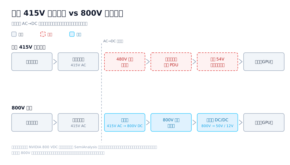
This table describes one route, not the only route. NVIDIA's August 2026 V2.0 white paper, 800 VDC Architecture: Industry Alignment & Execution, divides deployment into three independently selectable options: Power Rack, a rack-level option that adds an 800 V power rack on top of existing AC distribution without changing the data-center electrical system, with volume production in the second half of 2026; Power Center, a cluster-level option with centralized rectification at the row end and row-level 800 V DC busway, planned for 2027; and DC Power Block, a data-hall-level option that converts grid power directly to 800 V DC. The first two retain the existing AC chain. Only the third changes to direct medium-voltage conversion.
The same white paper also makes clear that 800 V DC is not intended to replace existing 415/480 V AC systems, but to coexist with them as a complement. It presents two implementations: TRU (transformer rectifier unit), based on a power-frequency transformer and still containing a step-down transformer and low-voltage rectifier stage, and SST (solid-state transformer), which uses high-frequency conversion to convert medium-voltage AC directly to 800 V DC. What disappears is the power-frequency transformer form, not "the transformer" itself.
The conclusion is that busway as a product category will not disappear, but its location and form will change—from "the thick copper bar inside the rack" to row-level and hall-level DC busways.
There is another division-of-function shift that is easy to miss. The function of the AC switchgear—dividing one incoming supply into multiple protected outputs—must move elsewhere. SemiAnalysis lists three candidates: a MW-scale integrated rectifier with multiple outputs and an SSCB on each output; a DC busway with circuit-breaker tap-off units; and a prefabricated gray-area module packaging a rectifier, distribution board, and busway. The second candidate has an explicit prerequisite: the arc-extinguishing capability of DC-rated tap-off units must become sufficiently mature.
What needs to be solved first when implementing a DC busway?
Arc extinction and interruption, tap-off capability, and completing the DC-specific standard verification items have already been discussed. Two other issues are easy to miss:
- Insulation and safety. Single-pole +800 V has a maximum conductor-to-ground voltage of 800 V, while bipolar ±400 V has 400 V to ground. Insulation thickness, creepage distance, and safety assessment requirements differ, so the topology must be fixed before selection.
- Conductor material. According to Delta's public product material, its 800 V DC busway is available with both copper and aluminium conductors. Aluminium is lighter and less expensive, but it needs a larger cross-section for the same current and places higher demands on joint workmanship, affecting busway dimensions and connector design.
The points above concern new-build or retrofit, ultra-high-density AI data centers. Conventional data centers will continue to use AC schemes in the short term because they are more mature; there is no need to retrofit them early for this reason.
Questions that still have no answer
As of 2026-09, the public sources searched for this article did not provide a clear basis for the following questions, so they are not presented as conclusions:
- Which will become mainstream, single-pole +800 V or bipolar ±400 V? Each route has different promoters, and their busway and protection schemes are not interchangeable. The choice directly determines which conductor-to-ground voltage to use for insulation design and cannot be deferred.
- How should the current-carrying-capacity table for DC busways be developed? AC busway capacity tables are measured at power frequency. DC has no skin effect, proximity effect, or reactive voltage drop. The same cross-section can theoretically carry more current, but public sources do not state clearly whether AC tables can be reused directly or whether correction factors are required. This is the most important question that this article cannot answer at present.
- How should DC interruption, insulation monitoring, and energized operation of tap-off units be tested, and to what level? NVIDIA's White Paper 2.0 only says that targeted updates are needed; it does not list specific verification items, and current standards do not appear to contain DC-specific test clauses.
- How long will AC and DC architectures coexist, and what will be the incremental cost of DC conversion? Claims of "parallel operation for 5–8 years" and "million-dollar-scale cost per MW" each come from a single source and cannot be cross-checked; this article does not use them.
Any judgment for which this article did not find public support is not included in the preceding conclusions.
Other common questions
Is an 800 V DC busway the same as the 240 V/336 V DC busways used in telecommunications?
No. They belong to the same family of high-voltage DC power-supply technologies, but their voltage levels differ. 240 V (YD/T 2378 series) and 336 V (YD/T 3089 series) are standardized and commercially deployed telecommunications systems; their busway forms and protection configurations are not at the same scale as 800 V DC.
References
All links below were accessed on 2026-09-16.
- NVIDIA technical blog, NVIDIA 800 VDC Architecture Will Power the Next Generation of AI Factories—source of the original "85% more power / 45% less copper" wording. https://developer.nvidia.com/blog/nvidia-800-v-hvdc-architecture-will-power-the-next-generation-of-ai-factories/
- NVIDIA, 800 VDC Architecture: Industry Alignment & Execution, White Paper V2.0 (2026-08-11)—source for the certification-strategy wording and SSCB positioning. https://www.nvidia.com/en-us/data-center/technologies/800-vdc-architecture/
- SemiAnalysis, Inside the 800VDC Revolution – Part 1 (third-party research)—source for the feeder-only busway forecast. https://newsletter.semianalysis.com/p/inside-the-800vdc-revolution-part
- National Public Service Platform for Standards Information: GB/T 7251.6-2015 entry and revision project notice (2026-07-27 to 2026-08-26). https://std.samr.gov.cn/gb/search/gbDetailed?id=71F772D80B58D3A7E05397BE0A0AB82A
- IEC 61439-6:2012 official scope description. https://webstore.iec.ch/en/publication/5463
- The Evolution in Data Center Power Distribution — PCIM Panel, Part 1 in Power Electronics News (2026-06-25)—record of the PCIM Europe 2026 roundtable. https://www.powerelectronicsnews.com/the-evolution-in-data-center-power-distribution-pcim-panel-part-1-the-transition-to-800-v
- Cloudmagazin, 800-Volt Direct Current in the Data Center (2026-06-17). https://www.cloudmagazin.com/en/2026/06/17/800-volt-direct-current-in-the-data-center-nvidias-pivot-for-the-cloud
- Delta Electronics 800 VDC product page and OCP Global Summit 2025 material (manufacturer's statement). https://www.delta-americas.com/en-us/news/deltas-groundbreaking-800-vdc-power-solutions-showcased-at-ocp-global-summit-2025-to-enable-sustainable-ai-factories
- Seven ministries, Implementation Plan for Promoting Coordinated Digital and Green Transformation Development (2026–2030) (2026-09-04). https://www.cac.gov.cn/2026-09/04/c_1790271981772781.htm
- China Academy of Information and Communications Technology: China's computing-infrastructure electricity consumption was about 170 billion kWh in 2025, approximately +30% year on year (reproduced by People's Daily Online). https://finance.people.com.cn/n1/2026/0909/c1004-40795381.html
This article is an industry observation and does not constitute procurement advice. | Updated 2026-09