
Conclusion
What is missing is not a standard, but the test-method layer within the standard system. Product-level specifications have been arriving in volume over the past three months, with indicators and inspection rules written down. But when the question becomes "how should insulation be tested under high-frequency operating conditions," the basis is still the waveform used for power-frequency transformers. The difference can be calculated: a pulse with a 100 ns rise time has a voltage slew-rate 31,831 times that of a 50 Hz power-frequency waveform, equivalent to a 1.59 MHz sine wave. Another industry addressed a similar problem twenty years ago—motors supplied by variable-frequency drives have a dedicated insulation standard that writes test waveform and rise time into the clauses.
Does the solid-state transformer lack standards? Which layer is missing?
The available documents look very different when divided by layer.
Association standards are the most concentrated. T/CAEE 102-2026, Solid-State Power Transformers—Part 1: Technical Specification, under the China Association for the Development of Electronic Equipment Technology, was published and implemented on 2026-08-26. It applies to AC/DC-conversion solid-state power transformers with a rated voltage of at least 1 kV and capacity of at least 10 kVA. T/CEATEC 237-2026, General Technical Specification for Solid-State Transformers, under the China-Europe Association for Technical and Economic Cooperation, was published and implemented on 2026-07-29 and includes technical requirements, functional requirements, test methods, and inspection rules. There are also standards for specific scenarios, such as the 2026 Solid-State Transformers—Part 1: Solid-State Transformers for Grid-Connected Photovoltaic Systems. At least three association standards for the same equipment class are running in parallel in the same quarter.
Industry standards are still on the way. According to a public introduction by participants in the standard-drafting process in May 2026, the energy-industry standards DC Transformers for DC Distribution Systems and Medium- and High-Frequency Isolation Transformers in Flexible Systems were "near the end of drafting" and expected to be published around the end of that year. Technical Specification for Medium- and High-Frequency Isolation Transformers and General Technical and Specification Requirements for Solid-State Transformers were still in application, with the participants estimating nearly two more years. Internationally, an IEC guidance standard on the performance of power-electronic transformers for flexible transmission and distribution was described at the time as "nearly complete," with publication expected at the end of the year or the following year.
There are many documents, but the missing piece is their level. A product standard says "what equipment should achieve"; a test-method standard says "what equipment and waveform should prove that it has achieved it." The first is being filled in, while the second has not caught up. At the same seminar, a speaker from Xi'an High-Voltage Apparatus Research Institute put it more directly than the public materials:
"The test technology for solid-state transformers is currently basically a blank."
Is the widely circulated "core general national standard GB/T 40429-2021 for SST" real?
No. In the national standards system, GB/T 40429-2021 is titled Classification of Driving Automation for Motor Vehicles. It was published on 2021-08-20 and implemented on 2022-03-01, under the National Technical Committee on Automobile Standardization, and divides automated driving into Levels 0 through 5. It has nothing to do with transformers.
The number has been attached to solid-state transformers more than once. Several public technical reviews and training materials call it "the core general national standard in the solid-state-transformer field" and even give an application scope and capacity range, making it look as though the text was copied from a standard. The number is real, and the title is real; putting them together is wrong. This kind of error is harder to notice than an entirely fabricated reference.
The speaker's survey provides a comparison: at national-standard level, he says that "the two standards currently available for reference" are an energy router functional specification and an electric-vehicle DC converter standard, both only related to solid-state transformers. From the perspective of participants in standards work, there is no dedicated general national standard for solid-state transformers. The qualification matters: this supports only the statement that no such national standard was found in the public material available at the relevant time; it cannot be turned into "one will never appear."
How different are power-frequency test methods from high-frequency operation?
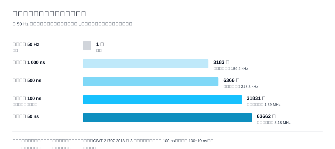
A power-frequency sinusoidal voltage at 50 Hz rises and falls slowly. Its voltage slew rate at the peak is 2πfU, where U is peak voltage. A medium- or high-frequency stage uses a square wave with steep edges, whose slew rate is approximately amplitude divided by rise time τ. Their ratio is:
Ratio = 1 ÷ (2πfτ)
The equation contains no voltage U—the difference is independent of voltage level and depends only on frequency and rise time. Calculate it for actual rise-time bands:
| Rise time τ | Multiple relative to power frequency | Equivalent power-frequency frequency |
|---|---|---|
| 50 ns | 63662 | 3.18 MHz |
| 100 ns | 31831 | 1.59 MHz |
| 500 ns | 6366 | 318.3 kHz |
| 1000 ns | 3183 | 159.2 kHz |
"Equivalent power-frequency frequency" means the frequency a 50 Hz sine wave would need to generate the same voltage slew rate: 159 kHz to 3.18 MHz. The frequency of the power-frequency test bench is 50 Hz.
One point must be separated out: voltage amplitude is not the whole insulation assessment. The insulation standard for motors supplied by variable-frequency drives writes frequency and rise time into the test waveform rather than specifying only a test voltage. Those two parameters enter the clause precisely because they affect the assessment result. Applying power-frequency voltage at the same amplitude gives insulation a slowly rising electric field; applying a kHz square wave to the same insulation subjects it to two steep transitions every cycle.
Boundary: this is an order-of-magnitude comparison, not a quantitative conversion of insulation life. The actual multiple depends on the device's real edge time; if a soft-switching topology makes the edge slower, the ratio decreases under the same formula.
Why increase frequency at all?
Because without increasing it, light weighting does not work.
The induced voltage of a transformer is proportional to frequency: with voltage, turns, and flux density held constant, core cross-section is inversely proportional to frequency. Raising frequency from 50 Hz to 20 kHz is a factor of 400, so in theory the cross-section could fall to one four-hundredth. But flux density cannot remain the same: oriented silicon steel is around 1.5 T, high-frequency ferrite is around 0.3 T (one-fifth), and nanocrystalline alloy is around 1.2 T (one 1.25th). Apply the correction:
| Magnetic-material assumption | Core cross-section relative to power frequency |
|---|---|
| Ferrite (flux density reduced to 1/5) | 1/80 |
| Nanocrystalline material (reduced to 1/1.25) | 1/320 |
| Ideal case (unchanged) | 1/400 |
Core cross-section can fall to 1/80–1/320 of the power-frequency core. This is the arithmetic behind the "large volume reduction" and the main hope for cost reduction. High-frequency operation is therefore not a route choice; it is the prerequisite.
The cost appears at the same time: core loss rises with frequency, approximately as frequency to the 1.2–1.6 power. If frequency is raised without reducing flux density in parallel, loss grows faster than volume benefit. Reducing volume and increasing insulation stress are two consequences of the same change—once frequency rises, the question "can the insulation withstand this fast voltage change, and how do we prove it?" must be answered.
Why are the new standards still using power-frequency methods?
The speaker states the reason directly: the partial-discharge test for medium- and high-frequency isolation transformers is being conducted at power frequency "because there is no standard and no research ... so our tests are still carried out under power-frequency conditions." More importantly, his assessment of the standard under development is:
"The Technical Specification for Medium- and High-Frequency Isolation Transformers ... still uses power-frequency transformer test methods for most of its provisions."
The old standard was not simply left unchanged; the new standard being written has also not crossed this step.
Why is it difficult? In the same material, he offers a method for solving an analogous problem that provides a useful scale. In converter-valve testing, the voltage waveform in the test circuit differs greatly from the actual operating waveform, but the test remains valid because the truly influential parameters—reverse-recovery peak and reverse-recovery time—are extracted and reproduced in the circuit. The criterion for equivalence is not "does the waveform look similar," but "have the key stress parameters been reproduced?"
Apply that to high-frequency insulation and the result is clear: the key stress parameters in high-frequency operation are voltage slew rate, switching frequency, rise time, and carrier ratio. These do not exist in a power-frequency test waveform and therefore cannot be reproduced. Reusing the waveform means changing the test condition to that of another system.
How has other high-frequency electrical equipment solved this, and can the approach be transferred?
Motors supplied by variable-frequency drives are in a highly similar situation to solid-state transformers: the internal waveform is PWM, insulation sees steep transitions, and early test methods also came from the power-frequency system. The industry's response was not to make the power-frequency method stricter, but to establish a separate specification and fix the test waveform.
Table 3 of GB/T 21707-2018, Insulation Specification for Three-Phase Asynchronous Motors for Variable-Frequency Speed Regulation, specifies a symmetrical bipolar square wave, steady-state impulse voltage of 3,000 V, frequency of 20 kHz, and rise and fall times of 100 ns. It also has a normative annex specifying measurement guidance for the waveform parameters of high-frequency impulse test instruments—even the permitted error of the test equipment's own waveform is controlled. In the same system, GB/T 22720.1, Rotating Electrical Machines—Qualification and Quality Control Tests for Type I Electrical Insulation Structures of Rotating Electrical Machines Fed from Voltage-Source Converters, corresponding to IEC 60034-18-41, treats the "converter-fed" condition separately for insulation qualification and type tests.
Three design actions are worth seeing clearly: replace the power-frequency sine wave with the pulse actually output by the equipment; classify insulation structures (Type I, which does not experience partial discharge over its life, and Type II, which does, with different assessment procedures); and define a new parameter linked to rated voltage—the impulse-voltage insulation class, IVIC—which the manufacturer specifies and marks on the nameplate. IVIC is a parameter created specifically for converter-fed operation; there is no equivalent in the power-frequency system.
These three actions can be transferred. They are independent of equipment form and depend only on the common premise that voltage changes rapidly. What cannot be transferred directly is the scope and subject: GB/T 21707-2018 applies to three-phase asynchronous motors with rated voltage up to 1,140 V and examines enamel, phase-to-phase, ground, and interturn insulation of windings. A solid-state transformer has another layer: it is a complete machine with rectification, isolation, and multiple output stages, while the medium- and high-frequency isolation transformer is only one stage. Core heating at high frequency, leakage-inductance control, and structural effects of vibration are additional issues that the speaker says remain under study.
The practical route is not to wait for one standard covering the entire machine, but to separate the layers: module-level, complete-machine, and on-site capacity tests, with a waveform and criterion agreed for each layer. Existing power-electronics methods—synthetic testing, back-to-back module testing, and grid simulators—can be used first. The tools are not missing; what is missing is writing the key waveform parameters into the clauses.
How should indicators be set and verified for a solid-state transformer today?
The practices below apply to procurement and acceptance negotiations before the standards are complete. They should be adjusted to the new standards once issued.
Efficiency indicators must include test conditions. Writing only "overall efficiency shall not be lower than a certain value" has little force because efficiency changes with load factor, input voltage, output waveform, and cooling conditions. At minimum, agree on the load factor, input/output form, and cooling conditions.
Request high-frequency operating data separately for insulation. A power-frequency partial-discharge value says nothing about the high-frequency stage: the voltage slew rates differ by three to four orders of magnitude. The supplier can be asked to provide partial-discharge data under a pulse waveform and state the rise time and frequency used in the test—there is no basis for comparison until the waveform parameters are provided.
Practical choice of acceptance basis. An association standard is independently developed and published by a social organization. Whether it can be used for acceptance depends on whether the contract cites it; once cited, it creates a project obligation. A type-test conclusion obtained using a power-frequency method still says something about power-frequency insulation, but it cannot serve as proof for the high-frequency stage.
Failure boundary: these are substitute arrangements for a gap in test methods, not equivalent test methods. They constrain whether high-frequency evidence has been provided, but do not guarantee that the severity of the evidence is sufficient. Once the relevant industry standard or IEC guidance standard is published and specifies a test waveform, the agreement should be revised to the new standard.
Questions that still have no answer
- There is no public quantitative life model for insulation degradation under high-frequency operation. The participants in drafting say that "no conclusion has yet been reached." It is not currently possible to turn "how many pulses can be withstood before failure" into a testable indicator.
- The equivalent test waveform has not been settled. A representative waveform, rise time, and cycle count must first be determined.
- Partial-discharge test conditions for medium- and high-frequency isolation transformers have not been unified. Public materials do not show a consistent voltage, waveform, and frequency basis.
- Standard numbers have become contaminated in circulation. In addition to the misattributed general national standard above, manufacturer pages list
GB/T 44287-2025, General Technical Conditions for Solid-State Distribution Transformers, andGB/T 44288-2025, Guidelines for Field Tests of Solid-State Distribution Transformers. Neither number appears in public searches of the National Standard Full-Text Publicity System or the National Public Service Platform for Standards Information. The pages that mention them also contain multiple data points that are difficult to verify. This article does not use them and cannot determine their authenticity from those pages. - The final content of the IEC guidance standard is not fixed. Before publication, it is impossible to know how granular its test provisions will be.
Other common questions
Can an association standard be used as an engineering acceptance basis? It is independently developed and published by a social organization, and its force comes from agreement between the parties. If the contract cites it, it is binding; if not, it is industry reference only.
Will solid-state transformers completely replace power-frequency transformers? Cost is a hard constraint. The seminar gives a figure of 3–10 times the cost of a conventional transformer; the ratio depends on the cost curve of power semiconductors and high-frequency magnetic materials.
References
- Xu Fan, "An Introduction to the Application of Power-Electronics Test Technology in Solid-State Transformers," 2026 New Power-System Online Seminar (Session 4, 46th session overall), transcript, 2026-05-22. https://www.sohu.com/a/1026297884_122655333
- North China Electric Power University, information for the 2026 New Power-System Online Seminar (speaker Xu Fan, Director of the Power Electronics Research Institute of Xi'an High-Voltage Apparatus Research Institute Co., Ltd.). https://www.ncepu.edu.cn/xshd/02465408afa34373ac2a21facf1ae2ae.htm
- National Digital Standards Library, entry for T/CAEE 102-2026, Solid-State Power Transformers—Part 1: Technical Specification. https://ndls.cnis.ac.cn/standard/detail/54f356262d49ee0989ef8c49c9e4f1dd
- National Association Standard Information Platform, entry for T/CEATEC 237-2026, General Technical Specification for Solid-State Transformers. https://www.ttbz.org.cn/standardDetail/7631939667424b40a945ae1552e9df14.html
- National Association Standard Information Platform, entry for Solid-State Transformers—Part 1: Solid-State Transformers for Grid-Connected Photovoltaic Systems. https://www.ttbz.org.cn/standardDetail/efa3243bca2f43edbe32ea7ba87810b1.html
- National Public Service Platform for Standards Information, GB/T 40429-2021, Classification of Driving Automation for Motor Vehicles. https://std.sacinfo.org.cn/gnoc/queryItemInfoPlat?projectId=116208; National Technical Standards Resource Service Platform, details for the same standard: http://c.gb688.cn/bzgk/gb/showGb?type=online&hcno=4754CB1B7AD798F288C52D916BFECA34
- GB/T 21707-2018, Insulation Specification for Three-Phase Asynchronous Motors for Variable-Frequency Speed Regulation, full text (Table 3, waveform parameters for high-frequency impulse testing of magnet wire). https://www.yiqifuwu.com/uploadfile/file/20200521/1590068835421488.pdf
- National Public Service Platform for Standards Information, project information for the national standard Rotating Electrical Machines—Qualification and Quality Control Tests for Type I Electrical Insulation Structures of Rotating Electrical Machines Fed from Voltage-Source Converters. https://std.samr.gov.cn/gb/search/gbDetailed?id=5DDA8B9DA37418DEE05397BE0A0A95A7
- National Digital Standards Library, IEC 60034-18-41:2014+AMD1:2019 entry. https://ndls.org.cn/standard/detail/de990c5411b68c904d2588ad8d61a145
- Shenyang Transformer Research Institute, Power-Electronic (Solid-State) Transformer Technology Development Seminar and Launch Meeting for Two Industry Standards Successfully Held in Qingdao. https://www.ctn.cn/info/1121/58686.htm
- GreenTest Technology, SST Solid-State Transformer Technology Overview: Definition, Characteristics, Standards, Application Scenarios, and Industry Landscape. https://www.greentest.com.cn/electron/sst-solid-state-transformer-technology-overview.html
This article is an industry observation and does not constitute procurement advice.