
The short answer
Triplen harmonics — the third, ninth, fifteenth and so on — arrive at the same phase angle in all three phases. In the neutral they add up instead of cancelling, and the neutral current comes to roughly three times the third-harmonic component. A three-phase four-wire circuit therefore cannot size its neutral on phase current alone. The 2009 edition of IEC 60364-5-52 — adopted in China as GB/T 16895.6-2014 — handles this with a two-column derating table: below 15% third harmonic the neutral may be smaller than the phase; above 33% the neutral must be selected on neutral current, which can make it equal to the phase conductor, or larger.
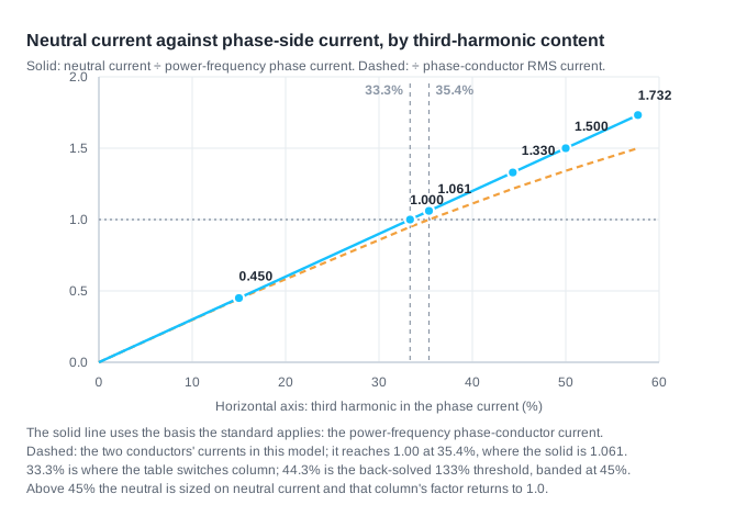
One thing is easy to get wrong here, and it is a matter of denominators. The third-harmonic content is a ratio to the fundamental, so what the estimate gives is a ratio to the power-frequency phase current, not to the phase conductor's own current.
Why don't triplen harmonics cancel in the neutral?
In a balanced three-phase four-wire circuit, the fundamental and the 5th and 7th harmonics sit 120° apart from phase to phase. Summed on the neutral, they come to zero. That is where the familiar line — "balanced three-phase, so no neutral current" — comes from, and for those components it holds.
The third harmonic behaves differently. At three times the fundamental frequency, three phases spaced 120° apart end up 3 × 120° = 360° apart, which is the same angle. Their contributions arrive in phase and add. Every odd multiple of three follows the same pattern — 9, 15, 21 and beyond.
What accumulates in the neutral is therefore not the residue of an unbalanced load but this family of zero-sequence components. The third harmonic is usually the largest of them, which is why it carries the estimate.
How much larger is the neutral current?
On a balanced load carrying only the fundamental and the third harmonic, the third-harmonic content is enough to estimate it:
I_N ≈ 3 × h₃ × I₁
Here h₃ is the ratio of the third harmonic to the fundamental in the phase current, and I₁ is the power-frequency phase current — the circuit design current taken in this example. In this model the phase conductor carries third-harmonic content too, so its RMS value I_lt = √(I₁² + I₃²) runs a little above I₁. The two are worth reading side by side:
| Third harmonic in phase current | Neutral current ÷ power-frequency phase current | Neutral current ÷ phase-conductor RMS (this model) |
|---|---|---|
| 15% | 0.450 | 0.445 |
| 33.3% | 1.000 | 0.949 |
| 35.4% | 1.061 | 1.000 |
| 44.3% | 1.330 | 1.216 |
| 50% | 1.500 | 1.342 |
| 57.7% | 1.732 | 1.500 |
The first column is the basis the standard uses when it asks whether neutral current exceeds phase current — Annex E says "the power-frequency current value in the phase conductor". The second column is the ratio between what the two conductors carry in this model. Both thresholds are real, and they are not the same number: treating them as one tilts the neutral's position either too high or too low.
Server racks, UPS outputs and switch-mode LED lighting are the usual harmonic sources. On such circuits the problem tends to sit in the neutral rather than in the phase conductor.
The derating table has two columns, not one
Annex E of IEC 60364-5-52:2009 — the edition GB/T 16895.6-2014 adopts — gives a derating table whose defining feature is that it is split into two columns:
| Third harmonic in line current | Size on line current | Size on neutral current |
|---|---|---|
| 0 – 15% | 1.0 | — |
| 15% – 33% | 0.86 | — |
| 33% – 45% | — | 0.86 |
| > 45% | — | 1.0 |
The split falls close to 33% third harmonic — the same point at which the neutral current catches up with the power-frequency phase current. Deciding which column applies comes before looking up a factor, and that order is easy to skip. Anyone who has memorised "harmonics, so apply a derating factor" will go on sizing by phase current on a circuit that should be sized by neutral current, and the left column's factor says nothing about the neutral.
The table carries one further boundary: it applies only to four-core or five-core cables, and only where the neutral and the phase conductor have the same material and the same cross-section. Confirm the object is a cable before reaching for it.
There is a version boundary as well: on the IEC side the table has already been replaced. Amendment AMD1:2024 reads "Annex E — replace the existing Annex E with the following new Annex E", a wholesale replacement. The new table's two columns are keyed to an equal-section or half-section neutral, with factors running from 0.99 to 0.71, and the amendment also replaces 524.2 and adds 524.3. The Chinese adoption GB/T 16895.6-2014 still uses the 2009 edition and has not followed, so this article is written against that one. If you hold the consolidated IEC edition, Annex E is no longer this table.
When is the neutral allowed to be smaller than the phase?
The conditions are cumulative, not alternatives:
- phase conductor larger than 16 mm² (copper) or 25 mm² (aluminium);
- load reasonably balanced in normal service, with harmonic current — including the third harmonic and its odd multiples — not exceeding 15% of the phase current;
- the neutral conductor protected against overcurrent as set out in IEC 60364-4-43:2008, clause 431.2;
- neutral conductor at least 16 mm² (copper) or 25 mm² (aluminium).
A table note adds that the reduction in the neutral's cross-section should generally not exceed 50% of the phase conductor's. Fail any one of the conditions and the neutral has to be at least as large as the phase. Single-phase two-wire circuits, and three-phase four-wire circuits whose phase conductor is 16 mm² copper or smaller, are not permitted a reduced neutral at all.
The same 2009 text carries a second rule alongside Annex E: for a multi-core cable whose third harmonic is above 33% and whose neutral is equal to the phase, size the neutral conductor on 1.45 times the phase current. It comes from the same document, phrased differently from the Annex E table. The public extracts reviewed here do not explain how the two are meant to be reconciled, so they are presented side by side below rather than resolved.
Why does the derating factor go back to 1.0 above 133%?
Above 45% third harmonic, the right-hand column gives 1.0 — no derating. That is not leniency; it is an account already settled.
Once the neutral current exceeds 133% of the power-frequency phase current, the cable has been sized on neutral current, so the three phase conductors are running below their rating. The heat they do not produce offsets the heat the neutral does produce, and the current-carrying capacity of the three loaded conductors no longer needs reducing.
This is also the step most often skipped. Keep sizing by phase current at this point and the cable is genuinely overloaded on the neutral. Whether that overload is ever noticed does not turn on a dedicated neutral breaker — the standard permits a neutral smaller than the phase only where the neutral is protected against overcurrent as set out in IEC 60364-4-43:2008, clause 431.2, and a neutral correctly sized for harmonics is already protected by the phase overcurrent device. What is genuinely at risk is a circuit where the neutral was not sized for harmonics, the phase protection does not reach it, and there is no neutral overload detection.
Working backwards through the formula above puts the 133% threshold at about 44.3% third harmonic; the table bands it at 45%. Both come from the same page, but they are not back-solved from one another — they differ by 0.7 of a percentage point.
Does the same rule apply to busbar trunking?
Not directly. Busbar trunking systems do sit inside this standard — IEC 60364-5-52 gives them their own subclause. But the derating table's scope sentence is explicit: four-core or five-core cables.
Applying that table to the neutral of a busbar trunking system is therefore a misuse. A busbar trunking system is an assembly: its rated current, temperature rise and short-circuit withstand are set by the product standard (IEC 61439-6 and its national adoptions), and the neutral's capability under harmonic current is a matter of type-test data and manufacturer derating information, not of a cable table.
The same harmonic physics, two different sets of criteria.
What does this mean for a data center row?
Take a row-level distribution circuit with a power-frequency phase current I₁ of 100 A (same model: balanced, fundamental and third harmonic only):
| Third harmonic | Neutral current | RMS phase-conductor current | Neutral ÷ RMS phase-conductor current |
|---|---|---|---|
| 15% | 45.0 A | 101.1 A | 0.445 |
| 33.3% | 100.0 A | 105.4 A | 0.949 |
| 35.4% | 106.1 A | 106.1 A | 1.000 |
| 40% | 120.0 A | 107.7 A | 1.114 |
| 50% | 150.0 A | 111.8 A | 1.342 |
The penalty is not linear. Conductor heating scales roughly with the square of current, so at 50% third harmonic the neutral runs at about 1.80 times the heating of the phase conductor (approximation: the two conductors have equal effective resistance and frequency-dependent resistance change is ignored). Comparing 150 A with 100 A directly would read as 2.25 times, but that denominator is the power-frequency current, not the current in either conductor. The upstream breaker is set on phase current: if the neutral's current-carrying capacity is insufficient, the phase protection cannot effectively protect it, and there is no neutral overload detection, the neutral can overload before the phase current trips anything.
The practical difficulty is that harmonic content is not a fixed design input. It is the outcome of which loads are combined. The same busway run feeding server power supplies and feeding resistive load gives two different answers, and that is what decides whether the neutral is sized normally or sized on neutral current.
Open questions
- The actual THD₃ distribution in data center circuits. It depends on the topology and loading of the rack power supplies. Published field statistics are scarce, and manufacturers quote typical values rather than distributions.
- Sizing when harmonics and unbalance occur together. The standard notes that a lower derating factor may be used, but gives no table for it; combining unbalance current and harmonic current in the neutral is left to the designer.
- The full numerical table in the new AMD1:2024 Annex E. The amendment is confirmed to replace Annex E wholesale — its two columns keyed to an equal-section or half-section neutral — but the public sample covers only part of it, so the new table has not been read cell by cell.
- How the 1.45-times rule relates to the Annex E table. Both come from the same standard, and the public extracts reviewed here do not say which governs. They are presented side by side, without a ruling.
- Harmonic derating data for busbar trunking neutrals. Manufacturers rarely publish a neutral derating curve against third harmonic; most quote rated current only.
References
All links accessed 2026-10-08.
- IEC Webstore, IEC 60364-5-52:2009+AMD1:2024 CSV — Low-voltage electrical installations – Part 5-52: Wiring systems. https://webstore.iec.ch/en/publication/103734
- CENELEC harmonisation document HD 60364-5-52:2011/A1:2025 (amendment to HD 60364-5-52:2011; its endorsement notice records that the text of IEC 60364-5-52:2009/AMD1:2024 was approved as a European Standard without any modification, with national implementation due 2026-01-31). https://standards.iteh.ai/catalog/standards/clc/cb1a8b5b-8189-43a8-a41e-2890dc8d2d7a/hd-60364-5-52-2011-a1-2025
- National Public Service Platform for Standards Information (China), entry for GB/T 16895.6-2014, which adopts IEC 60364-5-52:2009. https://openstd.samr.gov.cn/bzgk/gb/newGbInfo?hcno=EDDE2DDF8B79930F2AACFA64F0DFBAF7
- Weifang Construction Engineering Consulting Institute, Harmonic Protection of the Neutral Conductor (transcribes Table E.52.1 and its scope note). http://wfsgtsczx.com/contents/7/365.html
- Electrical Engineers' Cooperation Group (EEO), IEC Express: Harmonic Protection of the Neutral Conductor. https://www.sohu.com/a/770208024_100098465
- 7.4 Conductor Selection (clause text on harmonic current and neutral conductor cross-section in three-phase four-wire circuits). https://firelaw.cn/catalog/153/detail/4871
This article is an industry observation and does not constitute procurement advice. | Updated 2026-10
How is the allowable harmonic current shared among multiple users?