
The short answer
A grid-following converter is not a transformer impedance: on the current-limit plateau it behaves as a controlled current source, clamped to about 1.2–1.5 times rated. Grid-forming units act as a voltage source in the first instants and are covered here only through a 2–3× multiplier. How much it adds depends on the capacity ratio and the transformer short-circuit impedance: the share is roughly k × u_k × S_pcs/S_tr. On a 1250 kVA transformer with u_k 6%, a 500 kVA grid-following unit pushes 30.07 kA to 31.15 kA, a share of 3.60%. At storage ratings around four tenths of the transformer and an impedance of 6%, the incoming and branch breakers here see unchanged currents, so the item to re-check is protection settings; bus withstand and any shared feeder are separate checks.
How does a converter's fault current differ from a synchronous machine's?
A synchronous machine's fault current follows its physical construction: subtransient reactance, excitation, rotor time constants. Once those are fixed, the current at a given fault point is predictable — typically 5 to 10 times rated and decaying exponentially.
A converter is a different problem. A June 2024 review by Pacific Northwest National Laboratory (PNNL) for the US Department of Energy, Impact of Inverter-Based Resources on Grid Protection (report PNNL-36069), groups its fault behaviour into four points in its Chapter 1: the sustained fault current is low because the power devices must be protected; an initial transient lasting 0.5 to 1.5 cycles comes first, and only then does the current settle at the converter's limit; the angle between voltage and current during the fault is set by the control strategy rather than by impedance; and the fault current usually carries no zero-sequence component while negative-sequence current is often partly or fully suppressed.
For grid-following control, two consequences follow. On the current-limit plateau it is a current source, so folding it into a short-circuit study as an "equivalent impedance" puts the wrong model in the calculation; and its output is a range set by the current limit in the firmware, not a tabulated constant. Grid-forming control is different: the same report states in Chapter 3 that "GFM-controlled IBRs function as voltage sources behind impedance", with current injection strongly dependent on network conditions. The calculation here covers only the first case.
How wide is that range? A 2023 paper in Energies (16(7):3130) on estimating that contribution puts the common range at 1.1 to 1.5 times rated current, and records a 1.06 to 1.2 rule of thumb in the same paper. Grid-forming units differ. A 2021 Sandia National Laboratories presentation, Controls and Fault Response of Inverter-Based Resources (OSTI 1884450), states on page 4 that current-based control in grid-following inverters limits current more aggressively (about 1.2 to 1.5 p.u.) than voltage regulation in grid-forming inverters (2 to 3 p.u.); the units listed there are 3 to 100 kW single- and three-phase units on a PHIL bench. Applied to a 500 kVA unit those figures are an order-of-magnitude reference, not a measurement. There is a third case for a close-in bolted three-phase fault: the converter may block, and its contribution falls to zero.
Where does the 1.5 times figure come from?
The figure most often quoted in Chinese practice is 1.5 times. Its source is clause 5.4 b) of State Grid's Design code for connecting distributed generation to the distribution network (2013 edition), which states that a converter-type distributed generation system's fault current is taken as 1.5 times rated current.
A version caveat belongs here. That clause comes from the 2013 edition, which has since been revised; this article quotes the 2013 wording and does not draw on the later edition. "Take 1.5 times" should therefore be read as an engineering convention, not as a value traceable to a current text.
Low voltage is not without dedicated standards: GB/T 43526-2023, on connecting user-side electrochemical storage to the distribution network, and GB/T 44114-2024, on operation and control for storage connected to the low-voltage distribution network, are both current and directly relevant. This article estimates the magnitude only and does not cite their interconnection clauses one by one; the expression below is one estimation route, not the only one.
How much current does a 500 kVA unit add to the LV bus?
Take a concrete case: a 1250 kVA transformer, 10/0.4 kV, short-circuit impedance 6%, 400 V on the LV side.
With the transformer alone, the three-phase fault current is S/(√3·U·u_k) = 1250 / (1.732 × 0.4 × 0.06) ≈ 30.07 kA, about 16.7 times the 1,804.2 A rated current. That is a nominal-voltage figure using transformer impedance only — not a design maximum: grid and cable impedance bring it down, while a voltage factor would raise it.
A 500 kVA, 400 V converter has a rated current of 500 / (1.732 × 0.4) = 721.7 A. At 1.5 times, the fault current is 1,082.5 A.
Added to the bus: 30.07 + 1.08 = 31.15 kA, a share of 3.60% of the transformer's fault current.
At 2.5 times, typical of a grid-forming unit, the current is 1,804.2 A and the share 6.00%, taking the total to 31.87 kA.
What determines the share?
Written as a general expression, with √3·U cancelling at the same voltage level:
I_pcs / I_k = k · u_k · (S_pcs / S_tr)
At u_k = 6% the coefficient is 0.09 (k = 1.5) or 0.15 (k = 2.5). That sentence turns "do we need to recalculate" into arithmetic: with this transformer's own fault current as the denominator, the effect scales with the storage-to-transformer capacity ratio and with the transformer's short-circuit impedance.
| Capacity ratio | Share (k=1.5) | Share (k=2.5) | Total (k=1.5) |
|---|---|---|---|
| 0.2 | 1.80% | 3.00% | 30.61 kA |
| 0.4 | 3.60% | 6.00% | 31.15 kA |
| 0.8 | 7.20% | 12.00% | 32.24 kA |
| 1.0 | 9.00% | 15.00% | 32.78 kA |
| 2.0 | 18.00% | 30.00% | 35.48 kA |
| 4.0 | 36.00% | 60.00% | 40.90 kA |
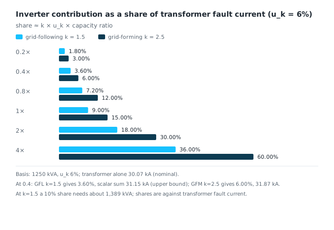
The direction of the impedance effect is easy to invert: a lower u_k means a higher transformer fault current, so the converter's share becomes smaller, not larger (6.00% at u_k 4%, 12.00% at u_k 8%, at a capacity ratio of 1). Adding grid and cable impedance shrinks the denominator and pushes the share up — the two effects must not be mixed.
The same expression runs backwards to answer "how much storage does it take to raise fault current by a tenth": S_pcs = target share × S_tr / (k · u_k). On a transformer with u_k 6%, reaching a 10% share takes 1,388.9 kVA at k = 1.5, or 1.11 times the transformer rating; at k = 2.5 it takes 833.3 kVA, or 0.67 times. For a 20% share the figures are 2,777.8 kVA (2.22 times) and 1,666.7 kVA (1.33 times).
This explains a common mismatch in expectations. Where the storage rating is around four tenths of the transformer — the ratio used here — the 1.5 times convention adds 3.60%. "Storage goes in and the fault current jumps" does not hold at that rating.
So must the breaker be replaced?
First the topology. In the usual arrangement the PCS ties through its own branch breaker to the same LV bus, and the fault is a bolted three-phase fault there: the transformer incoming breaker carries only 30.07 kA, and paralleling the PCS does not change it; the PCS branch breaker carries only 1.08 kA; the two meet at the fault point, where the scalar sum is 31.15 kA — the total at one point, not the current through any breaker.
So the replacement question is per position: both breakers see unchanged currents, the bus itself must be checked against 31.15 kA (a breaker's Icu does not stand in for bus withstand), and only a shared downstream feeder sees the combined current. The 31.15 kA is a scalar sum, an upper bound; at 90° the two components give 30.09 kA, a counter-example rather than the actual value. Exceeding the rating means "this screening cannot confirm compliance", not "the device must be replaced".
- Protection settings. An overcurrent stage set from the transformer rating barely notices a 3.60% increment in pickup; the effect appears at the sensitivity check at the far end.
- Selectivity. Where the time grading was already tight, an added current source changes the fault current distribution, and the grading has to be recalculated.
When does the order of magnitude actually change?
Two cases.
The first is multiple units. Four 500 kVA units (2 MVA in total, a capacity ratio of 1.6) with grid-following control give a share of 14.40% and a total of 34.40 kA; eight units (4 MVA, a ratio of 3.2) with grid-forming control give 48.00% and 44.50 kA.
The second is grid-forming control. The same 500 kVA unit gives 6.00% at 2.5 times against 3.60% at 1.5 times, a factor of 1.67. The voltage-source behaviour of a grid-forming unit in the first instants of a fault produces more current, which is why the two control modes cannot share one set of protection settings.
Eight grid-forming units (4 MVA, ratio 3.2) give a sum of 44.50 kA against 36 kA but at 90° a phasor sum of 33.355 kA: that point needs its own study, and it does not prove the breaker is inadequate. The denominator also matters — 48.00% is against the transformer current; against the scalar sum it is 32.43%.
If the share is so small, why recalculate protection at all?
The converter is rated 721.7 A and delivers 1,082.5 A during a fault, 1.50 times rated. A definite-time overcurrent stage is assumed here at 1.2 to 1.3 times rated: at 1.2 times the fault current is 1.25 times the setting, at 1.3 times it is 1.15 times. Whether that is enough is a separate question.
Those two figures — 25% and 15.4% above the assumed thresholds — are ratios to those thresholds, not operating margins: reliable operation needs the element's curve, tolerance and fault duration, none of which is given here. The operating mode has to be stated too — a grid-following converter cannot form a grid on its own, so island operation needs another grid-forming source or a change of control mode, which the 1.5 figure here does not cover.
When does this method fail?
- Single-phase faults. The contribution depends on whether the converter supplies negative-sequence current and has a neutral connection; this article covers bolted three-phase faults only.
- Converter blocking. A close-in fault can take the contribution to zero, and magnitude-based protection may reset.
- Initial transient. The spike within 0.5 to 1.5 cycles can exceed 2 times rated; the steady limit is used here.
- Arcing faults. Arc impedance lowers the current, so the result differs from the bolted case.
Open questions
- What the revised edition of the design code takes for converter fault current, which is outside what this article quotes.
- A general value for single-phase fault contribution, which depends on control strategy and wiring.
- The fault waveform of a given vendor's unit, including angle and negative-sequence suppression, comes only from vendor models or tests.
References
All links accessed 2026-10-22.
- Pacific Northwest National Laboratory, Impact of Inverter-Based Resources on Grid Protection: A Review of Negative-Sequence Current Generation (PNNL-36069), June 2024. https://www.pnnl.gov/main/publications/external/technical_reports/PNNL-36069.pdf
- State Grid Corporation of China, Design code for connecting distributed generation to the distribution network, clauses 5.4 and 5.6.1 (2013 edition, superseded by the 2017 edition). https://zjjcmspublic.oss-cn-hangzhou-zwynet-d01-a.internet.cloud.zj.gov.cn/jcms_files/jcms1/web3558/site/attach/0/981941cd43f44aa691afa5f704ca7780.pdf
- Energies 16(7):3130, "Estimation Method of Short-Circuit Current Contribution of Inverter-Based Resources for Symmetrical Faults", 2023. https://www.mdpi.com/1996-1073/16/7/3130
- EE Power School, "Inverter Fault Current Contribution and What It Breaks in Protection". https://eepowerschool.com/protection/inverter-fault-current-protection/
- Sandia National Laboratories, Controls and Fault Response of Inverter-Based Resources, 2021. https://www.osti.gov/biblio/1884450
- GB/T 43526-2023, Technical requirements for connecting user-side electrochemical energy storage systems to the distribution network. https://std.samr.gov.cn/gb/search/gbDetailed?id=0DF2F72AE3DB403DE06397BE0A0A87C4
- GB/T 44114-2024, Specification of operation and control for connecting electrochemical energy storage systems to the low-voltage distribution network. https://std.samr.gov.cn/gb/search/gbDetailed?id=19B8508AED554286E06397BE0A0A616D
This article is an industry observation and does not constitute procurement advice. | Updated 2026-10