
The short answer
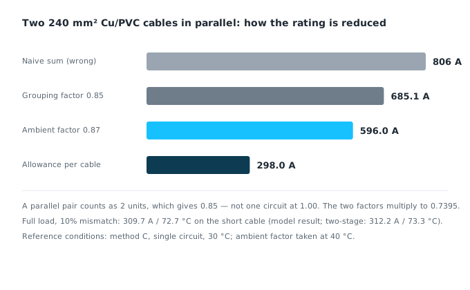
No. Two cables run side by side heat each other, so the tabulated rating is multiplied by a grouping factor. In the standard table a parallel pair counts as 2 units, which gives 0.85, and the ambient temperature factor applies on top of that. Take 240 mm² copper with PVC insulation, method C, one circuit, the two cables touching, no other circuits on the tray, 40 °C ambient: the single-cable rating at the 30 °C reference is 403 A and the pair carries 596.0 A, which is 26% below the 806 A arithmetic sum at the 30 °C reference. Of that 26%, mutual heating accounts for 15.0% and the ambient correction for 11.0%. The table also assumes equally loaded cables. Once the two lengths differ, the shorter one takes more current: a 10% mismatch brings it to 72.7 °C in the linked electro-thermal solution used here — a model result, not a measurement.
Two 240 mm² cables in parallel: how much can they actually carry?
Take a typical low-voltage feeder: 240 mm² copper, PVC insulation, three loaded conductors, single layer on a wall or an unperforated tray, one circuit, 30 °C ambient. Table B.52.4 of IEC 60364-5-52:2009 (Low-voltage electrical installations – Part 5-52: Wiring systems) puts the single-cable rating at 403 A for those conditions.
The intuitive sum is 2 × 403 = 806 A. That step treats the two cables as if each one dissipated heat on its own. They do not — they touch.
The 806 A figure is the arithmetic sum at the 30 °C reference; at 40 °C a single cable is down to 350.6 A and two independent cables would add to 701.2 A. Site discussions start from "rating × 2", so it is kept as the comparison: the 26.0% gap splits into 15.0% from mutual heating and 11.0% from ambient temperature.
In a group, the heat from each cable raises the air temperature around its neighbours, so each cable sheds less heat than it would alone. Table B.52.17 of IEC 60364-5-52, row 2 (single layer on a wall, floor or unperforated tray, cables touching), gives these factors:
| Units counted (circuits or multi-core cables) | 2 | 3 | 4 | 6 |
|---|---|---|---|---|
| Grouping factor | 0.85 | 0.79 | 0.75 | 0.72 |
| Net multiple (cables × factor) | 1.70 | 2.37 | 3.00 | 4.32 |
The first row deserves a pause. The table heading counts "circuits or multi-core cables": one multi-core cable is one unit, and two multi-core cables in parallel are therefore two units. A parallel pair takes the 0.85 value, not 1.00. Treating the pair as a single circuit would amount to claiming that the two cables do not heat each other.
Ambient temperature then applies. Table B.52.14 of the same standard gives, for PVC insulation in air, 1.00 at 30 °C and 0.87 at 40 °C.
So the pair is good for 403 × 2 × 0.85 × 0.87 = 596.0 A. The two factors multiply — 0.7395 in total — and each cable is left with 298.0 A, which is 74.0% of its standalone rating.
| Method | Result | What it misses |
|---|---|---|
| Naive sum | 806 A | Mutual heating and ambient temperature |
| Grouping only (30 °C) | 685.1 A | Ambient temperature |
| Grouping × temperature (40 °C) | 596.0 A | Nothing further; 298.0 A per cable |
The real threshold is a footnote: "equally loaded"
Note 1 to Table B.52.17 of IEC 60364-5-52 reads: "applicable to uniform groups of cables, equally loaded". That is a condition, not a courtesy. It limits the table to groups in which every cable carries the same share of the load.
Unequal lengths do not meet that condition: current divides inversely with impedance, so the shorter cable always takes more. At that point multiplying by a factor is no longer enough: the current split has to be calculated first, and the temperature checked afterwards.
Put another way, one cable running hot and the pair having to carry less total current are the same finding: keep the total at 596.0 A and the hottest cable is already over the limit; to keep it inside, the pair has to carry less.
The standard handles this in clause 523.7 of IEC 60364-5-52. Where two or more conductors are connected in parallel, arrangements must be made so that the current is shared equally; conductors of the same material and cross-section, of approximately equal length, with no branch along the route, may be considered to satisfy that requirement. The clause closes with a further point: where an equal share cannot be achieved, or where four or more conductors are connected in parallel, busbar trunking should be considered.
"Approximately equal" comes without a number. That leaves the quantitative work to the designer.
How much length mismatch pushes one cable over temperature?
Let the short cable run length L and the long one L(1+δ). Resistance is proportional to length, so the current divides inversely:
I_short / I_total = (1+δ) / (2+δ)
With the pair at its 596.0 A limit — a reference value only, since the table does not cover unequal pairs — the numbers are:
| Length mismatch δ | Short-cable current | Share of total | Overload vs 298.0 A | Conductor temperature |
|---|---|---|---|---|
| 0 | 298.0 A | 50.00% | 0 | 70.0 °C |
| 2% | 301.0 A | 50.50% | 0.99% | 70.7 °C |
| 5% | 305.3 A | 51.22% | 2.44% | 71.7 °C |
| 10% | 312.2 A | 52.38% | 4.76% | 73.3 °C |
| 20% | 325.1 A | 54.55% | 9.09% | 76.5 °C |
The overload has a compact approximation: relative to a fully loaded pair it is about δ/(2+δ). A 10% mismatch gives 4.76%, a 20% mismatch gives 9.09%.
The temperature column is not the result of scaling temperature rise by I². Resistance rises with temperature, so the heat balance I²·R(T) = k·(T − T_amb) is solved, with k calibrated at "298.0 A gives 70 °C in 40 °C ambient".
That column closes only half the loop: it fixes the current split by length and then treats current as constant. Once the two conductors sit at different temperatures the resistance ratio is no longer the length ratio, so the current must be re-shared. Solving the three relations together — I₁ + I₂ = total, I₁·R₁(T₁) = I₂·R₂(T₂), and a heat balance on each — gives 309.7 A / 72.7 °C on the short cable and 286.4 A / 67.5 °C on the long one at δ = 10% (unit-length balance). The two-stage figures, 312.2 A / 73.3 °C, leave the two branch voltage drops about 2.06% apart: they are not a steady-state solution of the same circuit.
One feedback is not modelled: mutual heating weakens as the split grows. Which way it moves the reading, and by how much, depends on the thermal field; no error bound given. 72.7 °C is a model result under fixed thermal coupling, not a measurement.
The baseline matters too. At "298.0 A per cable × 2" the conductor already sits at 70.0 °C with no margin, and a 10% mismatch pushes it to 72.7 °C, 2.7 K over. At an 80% load factor the same mismatch stays inside the limit — the conclusion applies to circuits designed at full load.
Why does the standard single out four or more conductors?
Look again at the net multiples: 1.70 for two cables, 2.37 for three, 3.00 for four, 4.32 for six. The usable share of each cable falls as the count rises: 0.85, 0.79, 0.75, 0.72.
The relative effect of an unequal split grows at the same time. With one short cable in a group of n, all others equal:
| Cables | Short-cable share | Ideal share | Relative overload |
|---|---|---|---|
| 2 | 52.38% | 50.00% | 4.76% |
| 3 | 35.48% | 33.33% | 6.45% |
| 4 | 26.83% | 25.00% | 7.32% |
For the same length mismatch, more cables mean a smaller ideal share per cable and therefore a larger relative overload on the short one. From four cables upward a second effect appears: the number of joints grows with the count, each crimp is an independent source of contact resistance, and equal sharing becomes harder to hold. Clause 523.7 names "four or more" conductors. The calculation above shows why sharing gets harder as the count rises, but it is a result of this model, not evidence of why the standard drew the line at four — no public drafting note for that clause was found up to October 2026.
Does spacing remove the derating?
Note 2 to Table B.52.17 of IEC 60364-5-52 provides an exemption: where the horizontal clearance between adjacent cables exceeds twice their overall diameter, "no reduction factor need be applied".
For a three-core cable of about 40 mm overall diameter (an assumed value, not a sample rating), the clearance must exceed 80 mm; expressed as centre-to-centre distance, more than 120 mm.
The exemption addresses mutual heating only. With equal length and a clearance above twice the diameter, the grouping factor becomes 1.00 and the pair is good for 403 × 2 × 0.87 = 701.2 A: the mutual-heating term is removed, the ambient term is not, so this is still only 87.0% of 806 A. Spacing does nothing about the split from unequal length — in the same-section, same-route case the split follows resistance, not cooling.
Is a parallel pair a spare?
Drawings often describe a pair as "two in parallel, one takes over if the other fails". Two different designs hide behind that sentence.
- If the total load is met by n cables in parallel — the case calculated here — the remaining cable has no extra capacity when one drops out. With no neighbour to heat it, the grouping factor returns to 1.00 and it is left with 403 × 0.87 = 350.6 A, which is 41.2% below the pair's 596.0 A. As a spare, the arrangement does not work.
- If the intent is N-1 redundancy, the rating must be checked on the remaining cables alone, with the grouping and temperature factors re-taken. That is a separate calculation, not a by-product of running cables in parallel.
There is also a risk pointing the other way. If the two ends are crimped to different standards, the spread in contact resistance can exceed the effect of length. No length tolerance controls that; only workmanship and measurement do.
When does this method fail?
- Mixed cross-sections. Current divides inversely with resistance, but ampacity grows more slowly than area, so the two load factors differ and which cable reaches its limit first depends on the pair. With 120 and 240 mm² (rated 259 A and 403 A at the 30 °C reference, a ratio of 1.556, no grouping or ambient factor on either) and a 2:1 current split, a total of 604.5 A puts the 240 mm² cable exactly at 403 A while the 120 mm² sits at 201.5 A, or 77.8% — the larger cable limits first. Neither direction can be assumed; work each case from its own data.
- Single-core cables in parallel. The counting differs: n single-core cables may be treated as n/2 circuits of two loaded conductors or n/3 circuits of three loaded conductors (Note 5). The calculation here is for multi-core cables.
- Short-circuit duty. Current sharing during a fault is a different problem from steady-state sharing, and the thermal withstand check is separate.
- Other circuits on the same tray. Only the heating between the two cables is counted here. With additional circuits on the tray, the grouping factor must be re-taken against the total circuit count and will be lower.
Open questions
- There is no public data on the statistical spread of contact resistance at crimped joints. How much it weighs against a length mismatch can only be measured on site; this article gives no ratio.
- The quantitative result for mixed cross-sections depends on the resistance and tabulated rating of the specific cables. No general factor exists.
- The acceptance value for "approximately equal length" is not numeric in the standard. Whether a project adopts 5% or 2% is a matter of its technical specification, and this article does not set that value for any project.
References
All links accessed 2026-10-22.
- IEC 60364-5-52:2009+AMD1:2024, Low-voltage electrical installations – Part 5-52: Wiring systems, clause 523.7, Tables B.52.4, B.52.14 and B.52.17. https://webstore.iec.ch/en/publication/103734
- GB/T 16895.6-2014, Low-voltage electrical installations – Part 5-52: Selection and erection of electrical equipment – Wiring systems (identical adoption of IEC 60364-5-52:2009), clause 523.7 and Annex B. https://openstd.samr.gov.cn/bzgk/gb/newGbInfo?hcno=EDDE2DDF8B79930F2AACFA64F0DFBAF7
- Schneider Electric, Electrical Installation Guide, "General method for cable sizing" (Fig. G16 reproduces Table B.52.17). https://www.electrical-installation.org/enwiki/General_method_for_cable_sizing
This article is an industry observation and does not constitute procurement advice. | Updated 2026-10