
The short answer
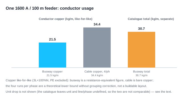
They differ on three quantities you can work out — conductor copper, unit voltage drop, space — plus one qualitative difference (how you extend them). On one 1600 A / 100 m feeder, on a like-for-like basis (both sides counted as 3L + 100% neutral, PE excluded): the busway's resistance-equivalent copper, back-calculated from the phase-conductor resistance, is about 21.5 kg/m; the cable set, 240 mm² clipped direct, four runs per phase, is about 34.4 kg/m — roughly 1.6 times as much (change the basis and the ratio moves; see below).
On voltage drop, the two sides cannot be placed side by side. The busway catalogue gives drop readings by power factor, but the heading does not state the unit or whether it is line or phase voltage. With no basis for the unit, this article does not turn it into a definite "volts per 100 m", and does not compare it against the cable; only the cable side is worked out.
Two limits come first: the cable's four runs are a "theoretical lower bound with no grouping correction", not a buildable configuration; and the two sides' bases differ (busway from a catalogue, cable from a model), so the numbers cannot simply be divided. Skip those two sentences and none of the rest holds.
Which quantities are we comparing?
Keep the scope as narrow as possible: one feeder — same rated current, same length. That leaves three quantities you can work out:
- Copper: how much copper the conductor uses per metre (kg/m). This one works on both sides, like for like.
- Unit drop: volts lost per 100 m (V/100m). This one works only on the cable side — the busway catalogue leaves the unit and the line/phase question open.
- Space: the clearances needed across and above (mm). This one works on both sides.
The fourth — extension, whether you add branches or raise capacity — can be distinguished but is not listed as a "workable quantity": whether it is feasible depends on the existing margin and protective coordination, so it is treated qualitatively here. Beyond these four — labour, cost, maintenance — nothing is treated as a computed figure.
On one 1600 A feeder, how far apart is the copper?
On the busway side the conductor section is not printed directly, but it can be back-calculated from the phase-conductor resistance: copper's resistivity at 20 °C is a fixed value, and resistivity over resistance per metre gives a resistance-equivalent section.
A = ρ20 ÷ R20
One published catalogue gives, at the 1600 A rating, a phase-conductor resistance of 28.73 μΩ/m — an equivalent section of about 600 mm² per phase. Counted as three phases plus a 100% neutral, that is about 2400 mm², or roughly 21.5 kg/m of copper. Two notes: this is a resistance equivalent — it folds in skin effect and joint resistance, so it is neither the geometric section nor the actual material mass; and the same catalogue rates the whole straight length at 30.7 kg/m (enclosure and insulation included, connectors listed separately), so "copper" and "total weight" are not the same thing.
The cable side works the other way round: first see what one 240 mm² copper cable can carry. In IEC 60364-5-52 Table B.52.4, clipped direct (method C) gives 403 A; direct buried (method D2) gives 320 A. Those two figures sit on one set of reference conditions — PVC insulation, three loaded conductors, copper, conductor temperature 70 °C, air 30 °C / ground 20 °C, single circuit — and change the conditions and they change. To reach 1600 A you need four runs per phase clipped direct (4 × 403 = 1612 A, under 1% margin). Add three phases and a 100% neutral: about 3840 mm², or roughly 34.4 kg/m — about 1.6 times the busway.
One limit must be stated: 403 A is a single-run ampacity under single-circuit reference conditions; run in parallel, the actual ampacity is below the sum of the individual runs. So "four runs per phase" is a theoretical lower bound with no grouping correction — build to that number and it may not be enough. A buildable configuration needs the grouping derating factor, which requires a defined installation and grouping arrangement.
Another comparison: in the same table a change of installation method alone drops the single-run ampacity from 403 A to 320 A, and the runs from four to five. So "how many cables" is not a property of the cable — it is decided by the installation method.
How do the drop and the space work out?
On drop, the basis still matters most — and here the two sides cannot be placed side by side. The busway catalogue gives drop readings by power factor (0.0528 at power factor 0.9), but its heading says only "Voltage drop U" and states neither the unit nor whether it is line or phase voltage. With no basis for the unit, this article does not use that reading against the cable, and does not turn it into a definite "volts per 100 m".
What can be worked out is the cable side, with the balanced three-phase line-voltage drop model:
ΔU_LL ≈ √3 × I × L × (R·cosφ + X·sinφ)
Fix the current at 1600 A, the length at 100 m and the power factor at 0.9 lagging, and take the conductor running temperature at 70 °C (the PVC condition of the ampacity table); correcting the 20 °C resistivity to that running temperature gives about 21.5 μΩ/m for four 240 mm² runs per phase. Let only the reactance move, since for parallel cables it is an assumed value. The result: about 5.4 V at zero reactance, about 6.6 V at 10 μΩ/m and about 7.8 V at 20 μΩ/m, all per 100 m. That is the cable side's sensitivity band; the busway side has no basis for its unit and is not in it.
On space, it takes two directions. The catalogue gives the 1600 A busway an outline of 125 × 190 mm — narrow across, tall above; the same feeder in 16 single-core cables side by side, at a hypothetical 28 mm diameter, needs about 448 mm across and about 28 mm above. Note this is a bare geometric envelope at an assumed diameter, not the installation clearance required; it excludes spacing, bending radius and maintenance access. The two occupy different directions of clearance; comparing area alone misleads.
Why can't "a busway carries X times a cable" be used directly?
Because ampacity has no single value — it depends on installation method, section, insulation and environment, and "X times" without the conditions is not a number at all.
In the public material this article searched (to 2026-10, one round each in Chinese and English), claims of the "several times the ampacity" and "less space" kind mostly give neither conditions nor sources, so they cannot be checked. They are noted only as background here, and this article does not rule on each of them — doing so would need to know what each one measures and under what conditions, which public pages usually leave out.
The workable form is the one used here: fix the current and the length, state the installation method, insulation and parallel rule, then give each quantity. The question "X times" only has a meaning once the basis is written down.
Which conditions does the site really have to separate?
Separating the workable quantities from the qualitative part, what a project has to separate is:
- Installation method: clipped direct or buried changes the runs needed (four versus five here).
- Conductor counting basis: whether PE is counted, and how much neutral and PE, changes one side's figure; with both sides on the same basis the ratio barely moves (here, with 50% PE on both sides, the ratio is still about 1.6). Count PE on one side only and the two ranges no longer match — that is not a like-for-like comparison.
- Which direction is tight: a shaft limited in height or a tray limited in width decides which shape fits.
- The two extension cases, kept apart:
- Adding a branch within the existing margin: total demand unchanged. The busway takes a tap-off unit on the existing run, the trunking itself unchanged; a cable branch usually means running a new circuit from the switchroom. This case assumes the feeder still has margin and that the tap-off rating and protective coordination hold.
- Raising total demand (one more step of capacity): this depends on the feeder's actual margin and protective coordination; a tap-off unit only adds a tap point and does not prove the existing feeder can carry the raised total, so no figure is given here.
Change any condition and the answer changes. This article supplies the method and one set of re-runnable figures; it does not conclude which to choose — that depends on the specific project's conditions and trade-offs.
Open questions
- A buildable cable configuration. The four runs per phase here are a theoretical lower bound with no grouping correction; the actual count depends on the installation and grouping and needs the grouping derating factor.
- The busway catalogue's drop unit definition. The heading says only "Voltage drop U" and states neither the unit nor line or phase voltage; the reading still needs a source, and until it has one the busway drop stays out of the comparison.
- The actual reactance of parallel cables. The reactance here is an assumed value, used only to give the cable side's drop sensitivity band.
- A cost conclusion. This article compares quantities only; labour, material prices and running costs are outside it.
- The busway's actual geometric section. The figure here is a resistance equivalent; its real geometric section and material mass were not obtained.
References
Accessed 2026-10-13.
- Published busway product catalogue (low-impedance sandwich type). https://library.e.abb.com/public/01d6d2c28d904d6cb5aca04409f43ae9/9AKK107045A3228_ABB_EPIP%20Product%20Pmax%20CT_DGT.pdf
- General method for cable sizing (table values, conditions and the voltage-drop formula per IEC 60364-5-52). https://www.electrical-installation.org/enwiki/General_method_for_cable_sizing
- Official consolidated record of IEC 60364-5-52:2009 and its amendment. https://webstore.iec.ch/en/publication/103734
- Busway product datasheet (3200 A, for background on the drop basis). https://www.se.com/id/en/product/KTA3200CP43/
This article is an industry observation and does not constitute procurement advice. | Updated 2026-10
How is a busway's rated current determined? How Do Short-Time and Peak Withstand Currents Pair Up?